Manual auxiliary support

A technology of auxiliary support and ejector rod, which is applied in the field of fixtures and fixtures, can solve problems such as size deviation, failure to achieve quick replacement, deviation, etc., and achieve the effect of ensuring flatness

Inactive Publication Date: 2016-01-13
东实汽车动力零部件(湖北)有限公司
View PDF1 Cites 4 Cited by
  • Summary
  • Abstract
  • Description
  • Claims
  • Application Information

AI Technical Summary

Problems solved by technology

Although the use of locking inclined blocks can lock the main shaft of the floating support, it requires a large external force, that is, tools are needed to ensure the locked state. For the quick-change floating support, the purpose of quick replacement cann...

Method used


Image

  • Manual auxiliary support
  • Manual auxiliary support
  • Manual auxiliary support

Examples


Embodiment Construction

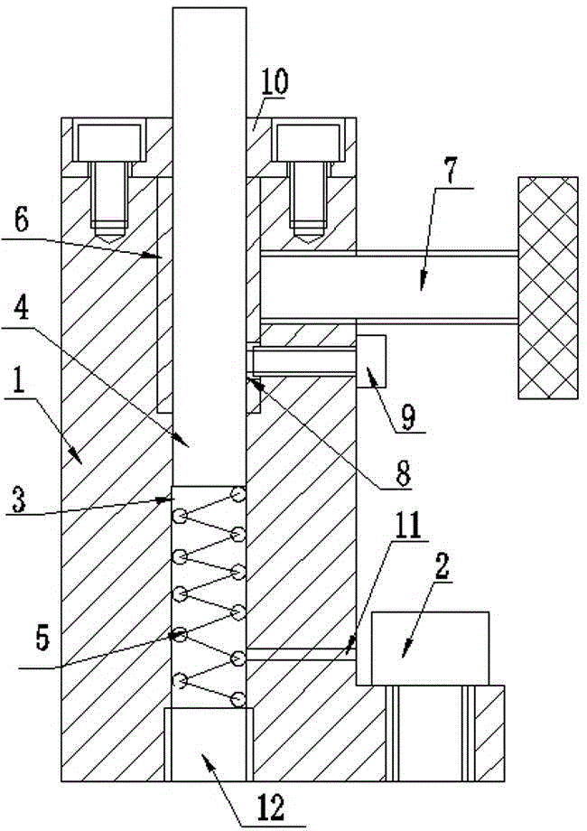
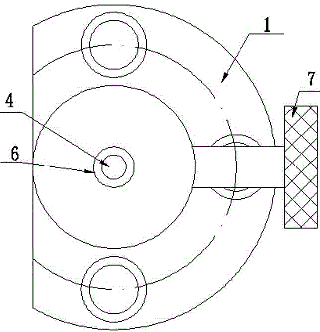
[0026] The invention as figure 1 , 2 shown.

[0027] The manual auxiliary support includes a base 1. Fixing bolts 2 are arranged around the bottom of the base 1. A guide hole 3 is vertically provided in the middle of the base 1. A push rod 4 is arranged in the guide hole 3. The lower part of the push rod 4 is installed. There is a spring 5; the push rod 4 protrudes from the guide hole 3 to the outside of the base 1, and the guide hole 3 is also provided with a jacket 6, and the push rod 4 is installed in the jacket 6, corresponding to the side wall of the base 1 The jacket 6 is provided with a locking screw 7 .

[0028] The jacket 6 is axially provided with clamping openings 13 .

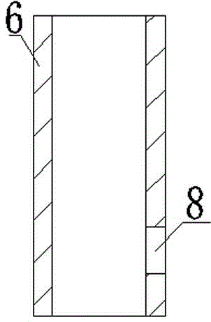
[0029] A positioning hole 8 is provided on the side wall of the jacket 6 , and a fixing screw 9 is provided on the side of the base 1 in cooperation with the positioning hole 8 .

[0030] A cover plate 10 is provided on the top of the base 1 , and the push rod 4 protrudes from the cover plate 10...


PUM


Abstract

The invention provides a manual auxiliary support. Fixing bolts are arranged on the periphery under a base. A guide hole is vertically formed in the middle of the base. An ejector rod is arranged in the guide hole in a matched mode. A spring is arranged under the ejector rod. The ejector rod stretches out of the base from the guide hole. A clamping sleeve used for clamping an opening is also arranged in the guide hole. The ejector rod is installed in the clamping sleeve in a matched mode. A locking screw corresponding to the clamping sleeve is arranged on the side wall of the base. A positioning hole is formed in the side wall of the clamping sleeve. A fixing screw matched with the positioning hole is arranged on the side face of the base. A cover plate is arranged at the top of the base. The ejector rod stretches out of the cover plate. An adjustment bolt is arranged at the bottom of the spring. An air outlet is further formed in the position, on the lower portion of the ejector rod, of the side wall of the base. According to the manual auxiliary support, the ejector rod has a floating supporting effect relative to the spring, the locking purpose can be achieved manually through surface contact of the clamping sleeve, and convenience and rapidness are achieved; the manual auxiliary support is mainly used for designing clamps for poor-rigidity parts such as thin-walled parts and parts in irregular shapes, rapid fixing and installing are achieved, the structure is simple, and the manual auxiliary support is economical and practical.

Description

technical field [0001] The invention relates to a tool fixture, in particular to a manual auxiliary support. Background technique [0002] At present, many flywheel housing products have the design of the oil pan surface. As a result, when turning the spigot surface, it is easy to cause vibration marks and flatness of the spigot surface to be out of tolerance due to the large overhanging part and no support. In order to solve this kind of problem, the only way to increase the rigidity of the clamping system is to increase the rigidity of the clamping system by adding elastic auxiliary support under the overhanging part, so as to avoid vibration marks and poor flatness of parts caused by cutting force deformation. The same is true for machining thin-walled parts and irregularly shaped parts. Therefore, auxiliary supports are increasingly used in fixture design. Auxiliary support is divided into hydraulic auxiliary support, pneumatic auxiliary support and manual auxiliary su...

Claims


Application Information

Patent Timeline
IPC IPC(8): B23Q3/00
Inventor 佀金生孙耀辉陈前胜
Owner 东实汽车动力零部件(湖北)有限公司
Why Eureka
Try Eureka