
Adjustable optical fiber welding device with fixing and skin cutting functions

An optical fiber fusion splicing and adjustable technology, applied in the field of communication optical fiber fusion, can solve the problems of increased difficulty in fusion splicing work, cumbersome fusion splicing process, troublesome operation, etc., and achieve the effect of convenient overall use and operation, high efficiency and good effect.

Inactive Publication Date: 2021-10-15
厦门祺刻贸易有限公司
View PDF0 Cites 0 Cited by
  • Summary
  • Abstract
  • Description
  • Claims
  • Application Information

AI Technical Summary

Problems solved by technology

[0002] Communication optical fiber is also called optical fiber communication, which refers to a way of transmitting information by using light and optical fiber, while optical fiber fusion is to connect optical fiber and optical fiber or optical fiber and pigtail, and fuse the bare fiber and optical fiber pigtail in the optical cable together to become As a whole, but the current optical fiber fusion splicing device still has the following deficiencies in actual use: 1. The existing optical fiber fusion splicing device is not convenient for fixing and limiting the optical fiber during actual use, which makes the welding work more difficult, and the fusion splicing The distance between the two optical fibers is inconvenient to adjust when fixed; 2. The existing optical fiber fusion splicing device needs to manually take out the fixed optical fiber and cut the skin of it in the actual use process, which is cumbersome to operate and makes the entire fusion splicing process cumbersome

Method used


Image

  • Adjustable optical fiber welding device with fixing and skin cutting functions
  • Adjustable optical fiber welding device with fixing and skin cutting functions
  • Adjustable optical fiber welding device with fixing and skin cutting functions

Examples


Embodiment 1

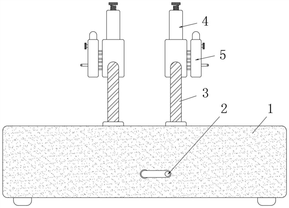
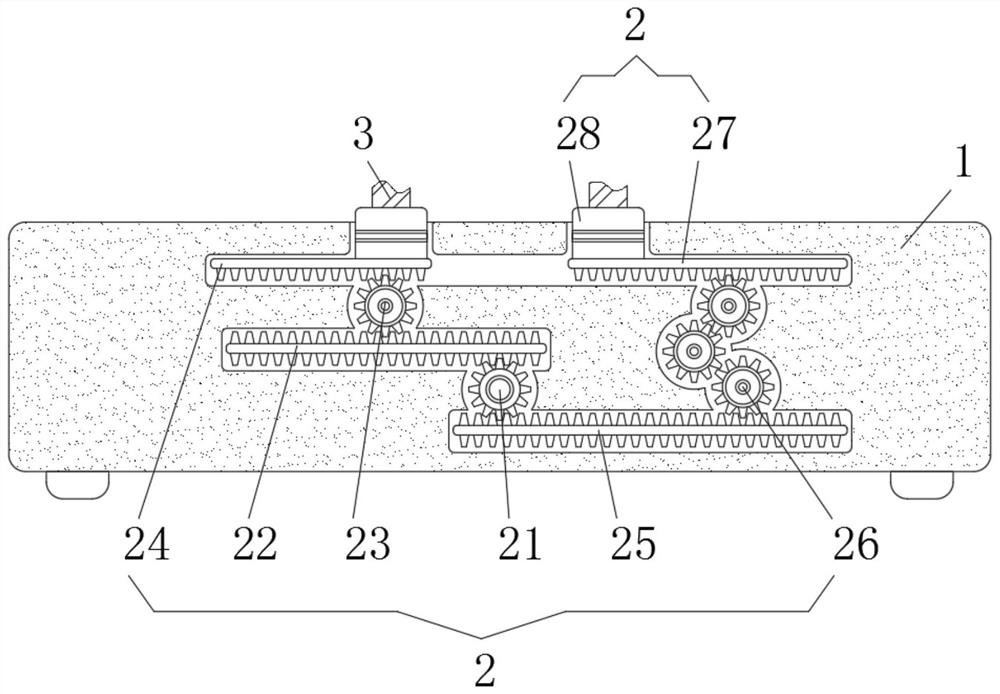
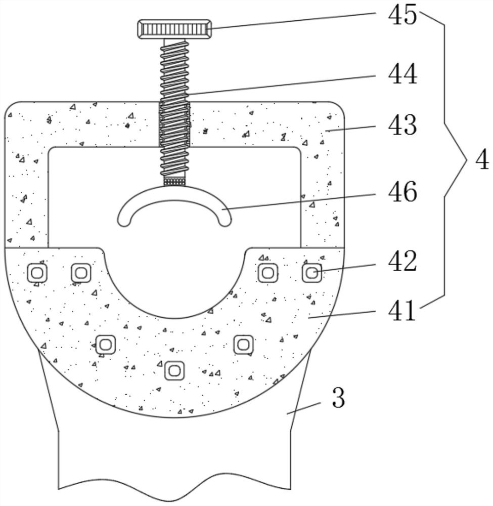
[0028] see Figure 1-3 , the inside of the base 1 is fixedly installed with a transmission mechanism 2, the top of the base 1 is fixedly installed with a mounting bracket 3, the top of the mounting bracket 3 is fixedly installed with a fixing mechanism 4, one end of the fixing mechanism 4 is fixedly connected with a skin cutting mechanism 5, and the transmission mechanism 2 includes gear one 21, tooth plate one 22, gear two 23, tooth plate two 24, tooth plate three 25, gear assembly 26, tooth plate four 27 and slide block 28, and the top of gear one 21 is meshed with tooth plate one 22 , gear two 23 is meshed above tooth plate one 22, tooth plate two 24 is meshed above gear two 23, tooth plate three 25 is meshed below gear one 21, and gear assembly 26 is meshed above the right end of tooth plate three 25 , the top of the gear assembly 26 is meshed with tooth plate four 27, the top of tooth plate two 24 and tooth plate four 27 is fixedly equipped with a slider 28, the surface o...

Embodiment 2

[0030] see figure 1 , 4, 5, 6, the inside of the base 1 is fixedly installed with a transmission mechanism 2, the top of the base 1 is fixedly installed with a mounting bracket 3, the top of the mounting bracket 3 is fixedly installed with a fixing mechanism 4, and one end of the fixing mechanism 4 is fixedly connected with a skin cutting mechanism 5. The epidermis cutting mechanism 5 includes a cutting main casing 51, a handle 52, a chute 53, a sliding installation block 54, a movable connecting rod 55, a cutting blade 56, a fixed tooth plate 57, a gear three 58 and a gear four 59, and the cutting main shell A handle 52 is fixedly installed on the surface of the body 51, a chute 53 is provided inside the cutting main housing 51, a sliding installation block 54 is slidably installed on the chute 53, and a movable connecting rod 55 is fixedly installed on one side of the sliding installation block 54, The surface of the sliding mounting block 54 is provided with a cutting blad...

Embodiment 3

[0032] see Figure 1-6 , the inside of the base 1 is fixedly installed with a transmission mechanism 2, the top of the base 1 is fixedly installed with a mounting bracket 3, the top of the mounting bracket 3 is fixedly installed with a fixing mechanism 4, one end of the fixing mechanism 4 is fixedly connected with a skin cutting mechanism 5, and the transmission mechanism 2 includes gear one 21, tooth plate one 22, gear two 23, tooth plate two 24, tooth plate three 25, gear assembly 26, tooth plate four 27 and slide block 28, and the top of gear one 21 is meshed with tooth plate one 22 , gear two 23 is meshed above tooth plate one 22, tooth plate two 24 is meshed above gear two 23, tooth plate three 25 is meshed below gear one 21, and gear assembly 26 is meshed above the right end of tooth plate three 25 , the top of the gear assembly 26 is meshed with tooth plate four 27, the top of tooth plate two 24 and tooth plate four 27 is fixedly equipped with a slider 28, the surface o...


PUM


Abstract

The invention provides an adjustable optical fiber welding device with fixing and skin cutting functions, and relates to the technical field of communication optical fiber welding. The adjustable optical fiber welding device with the fixing and skin cutting functions comprises a base, a transmission mechanism is fixedly mounted in the base, a mounting bracket is fixedly mounted at the top of the base, and a fixing mechanism is fixedly mounted at the top of the mounting bracket. According to the adjustable optical fiber welding device with the fixing and skin cutting functions, the transmission mechanism and the fixing mechanism are arranged, so that an optical fiber needing to be welded can be effectively fixed and limited in actual use, and due to the characteristic that adjustment is convenient, the device is convenient to use; and by arranging the skin cutting mechanism, the whole device is very convenient to use and operate, the skin cutting effect is good, the efficiency is high, and the problems that traditional skin peeling needs manual operation, and the treatment efficiency is low are solved.

Description

technical field [0001] The invention relates to the technical field of communication optical fiber welding, in particular to an adjustable optical fiber welding device with functions of fixing and skin cutting. Background technique [0002] Communication optical fiber is also called optical fiber communication, which refers to a way of transmitting information by using light and optical fiber, while optical fiber fusion is to connect optical fiber and optical fiber or optical fiber and pigtail, and fuse the bare fiber and optical fiber pigtail in the optical cable together to become As a whole, but the current optical fiber fusion splicing device still has the following deficiencies in actual use: 1. The existing optical fiber fusion splicing device is not convenient for fixing and limiting the optical fiber during actual use, which makes the welding work more difficult, and the fusion splicing The distance between the two optical fibers is inconvenient to adjust when fixed;...

Claims


Application Information

Patent Timeline
IPC IPC(8): G02B6/255G02B6/245
CPCG02B6/2555G02B6/245
Inventor 裘轲
Owner 厦门祺刻贸易有限公司
Learn More