
High-efficiency centrifugal water pump

A centrifugal water pump, high-efficiency technology, applied to pumps, pump devices, pump components, etc., can solve problems such as energy waste, high dimensional accuracy requirements, and increased processing costs

Inactive Publication Date: 2015-03-11
CHINA NORTH ENGINE INST TIANJIN
View PDF4 Cites 1 Cited by
  • Summary
  • Abstract
  • Description
  • Claims
  • Application Information

AI Technical Summary

Problems solved by technology

At present, the efficiency of water pumps in the domestic water pump industry, especially in the agricultural irrigation industry, is generally around 30% to 45%. Although the price is low, the energy waste is serious.
[0003] In order to improve the efficiency of the water pump, in addition to using computer-aided optimization of the internal flow field of the water pump during design, the main method is to improve the machining accuracy and minimize the backflow of water in the side clearance of the impeller. The corresponding requirement is that the clearance between the impeller and its mating surface is very small, generally 0.8 ~1.2mm, resulting in high requirements for the dimensional accuracy of the parts of the water pump, which increases the processing cost

Method used


Image

  • High-efficiency centrifugal water pump

Examples


Embodiment Construction

[0018] Specific embodiments of the present invention will be described in detail below in conjunction with the accompanying drawings.

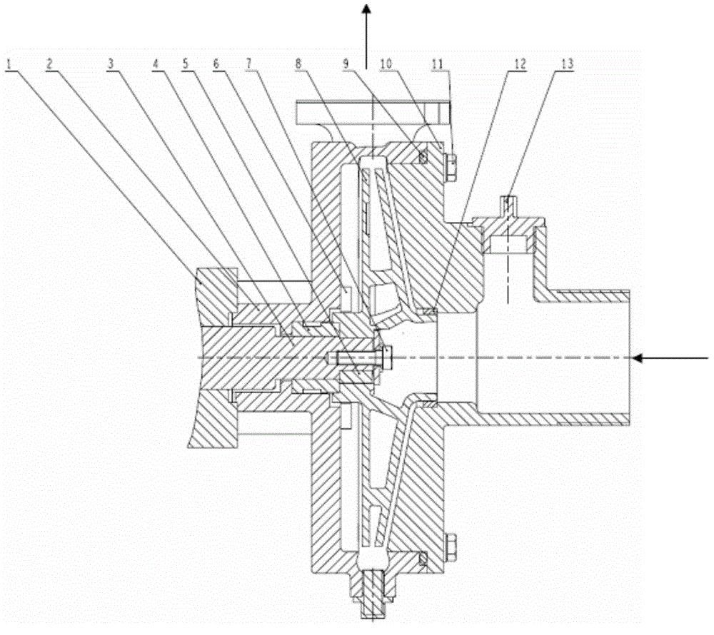
[0019] A high-efficiency centrifugal water pump, such as figure 1 As shown, it includes a volute 2, a water seal 4, a closed impeller 8 and a water inlet plate 10. The volute 2 is fixed on the gasoline engine 1 through a connecting bolt 6, and the water inlet plate 10 is fixed on the On the volute 2, an impeller chamber is formed between the water inlet plate 10 and the volute 2, and a closed impeller 8 is arranged in the impeller chamber, and the closed impeller 8 is connected with the output shaft 3 of the gasoline engine through a key 5; the water seal 4 is arranged on Between the inner surface of the volute 2 and the gasoline engine output shaft 3 of the gasoline engine 1, and one end of the water seal 4 is in contact with the closed impeller 8; the water inlet plate 10 is provided with a water inlet on the front side, and a water injectio...


PUM


Abstract

The invention provides a high-efficiency centrifugal water pump. The high-efficiency centrifugal water pump comprises a volute, a water seal, a closed impeller and a water inlet receiving disc, wherein an impeller chamber is formed between the water inlet receiving disc and the volute; the closed impeller is arranged in the impeller chamber, and is fixed on a gasoline engine output shaft of a gasoline engine; a seal cartridge is arranged between the water inlet receiving disc and the closed impeller; and the seal cartridge and the closed impeller are in dynamic seal to prevent the communication of high-pressure and low-pressure water cavities in the impeller chamber and to achieve a floating support effect on the closed impeller. The high-efficiency centrifugal water pump has the following advantages and beneficial effects: as the seal cartridge is arranged, a high-pressure cavity is formed in a water outlet area of the closed impeller, and a low-pressure cavity is formed in a water inlet area of the closed impeller for isolating, the front and back surfaces of the closed impeller are both positioned in the high-pressure cavity, the axial force is self-balanced, the influence of an impeller side gap on the efficiency of the water pump is eliminated, and the efficiency of the water pump is improved; and the side gap of the closed impeller has no influence on the performance of the water pump, so that the size precision requirements of all parts of the water pump are largely reduced, and the processing cost is reduced.

Description

technical field [0001] The invention belongs to the technical field of centrifugal water pumps, in particular to a high-efficiency centrifugal water pump in which a closed impeller is supported by radial floating and reliably sealed. Background technique [0002] As an important fluid mechanical equipment in the country's industry and agriculture, water pumps play a pivotal role in economic development. At present, the efficiency of water pumps in the domestic water pump industry, especially in the agricultural irrigation industry, is generally around 30% to 45%. Although the price is low, the energy waste is serious. [0003] In order to improve the efficiency of the water pump, in addition to using computer-aided optimization of the internal flow field of the water pump during design, the main method is to improve the machining accuracy and minimize the backflow of water in the side clearance of the impeller. The corresponding requirement is that the clearance between the ...

Claims


Application Information

Patent Timeline
Patent Type & Authority Applications(China)
IPC IPC(8): F04D13/02F04D29/08F04D29/66F04D29/28
CPCF04D13/02F04D29/106F04D29/167F04D29/20F04D29/669
Inventor 宋吉林甄洪梅陈晓飞葛玉霞王红丽马军华王旭兰任伟
Owner CHINA NORTH ENGINE INST TIANJIN
Learn More