
Twin-spindle numerical-control device used for composite sliding block machining

A numerical control device and dual-spindle technology, applied in metal processing, metal processing equipment, manufacturing tools, etc., can solve the problems of high product defect rate, poor quality, low processing efficiency, etc., to reduce product defect rate, reduce production costs, The effect of improving machining accuracy

Inactive Publication Date: 2016-01-13
JIANGMEN INTIN NUMERICAL CONTROL MACHINE TOOL CO LTD
View PDF10 Cites 3 Cited by
  • Summary
  • Abstract
  • Description
  • Claims
  • Application Information

AI Technical Summary

Problems solved by technology

In the prior art, to carry out the above-mentioned processing, some use a variety of mechanical processing equipment and workers to cooperate, the processing efficiency is low and the quality is poor, and some use a general-purpose processing center plus a fourth-axis turntable fixture to cooperate, the processing efficiency is low and the production cost is low. high
Moreover, in the drilling process of the slider, the above-mentioned processing methods are to process one end face first and then the other end face. It is difficult to control the symmetry of the processing, and the factors of manual clamping and adjustment are greatly affected, resulting in a high defect rate of the product.

Method used


Image

  • Twin-spindle numerical-control device used for composite sliding block machining
  • Twin-spindle numerical-control device used for composite sliding block machining
  • Twin-spindle numerical-control device used for composite sliding block machining

Examples


Embodiment Construction

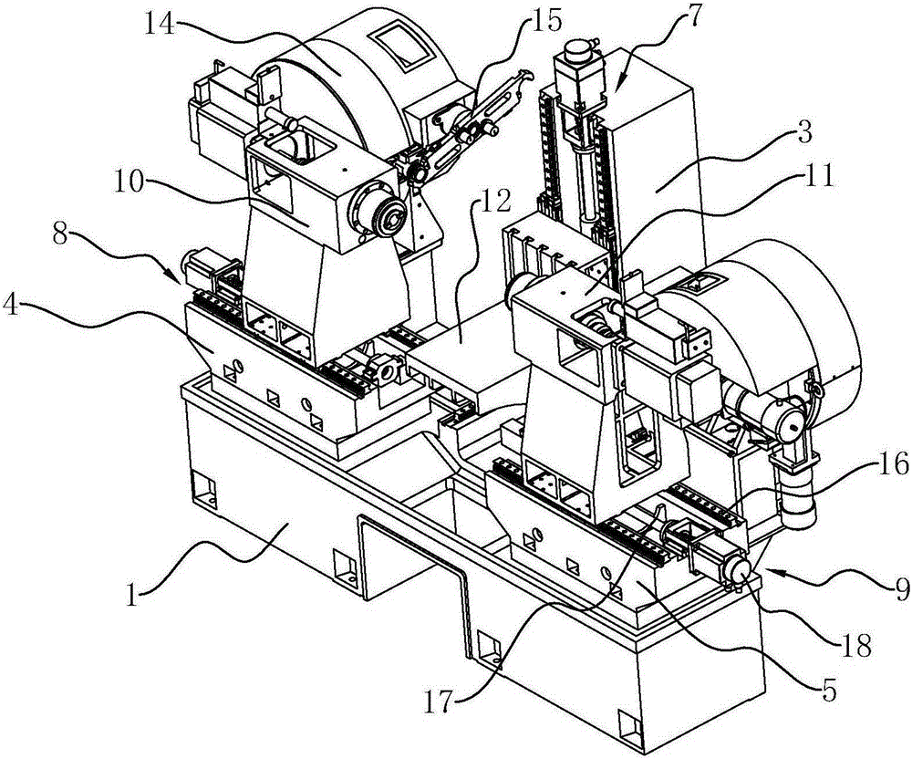
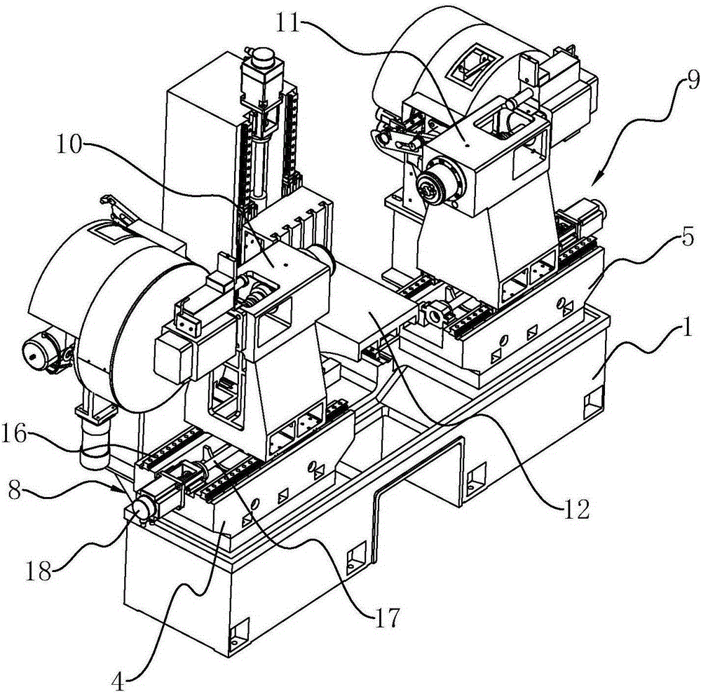
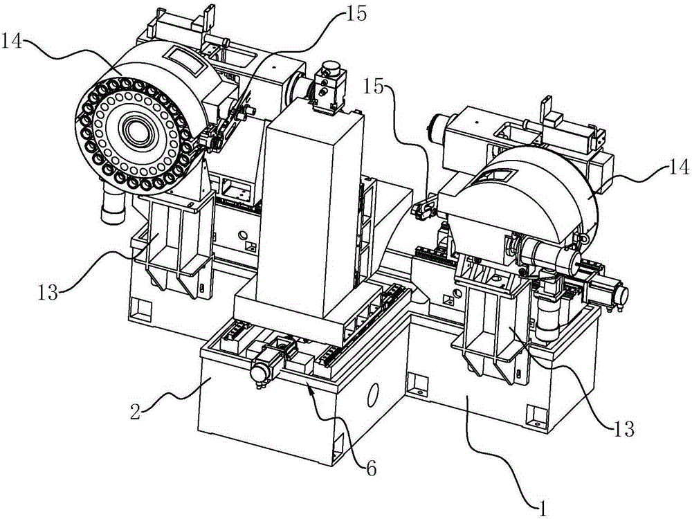
[0013] refer to Figure 1 to Figure 3 , a dual-spindle numerical control device for composite machining of sliders according to the present invention includes a base 1 on which X-axis, Y-axis and first and second Z-axis support seats 2, 3 are installed respectively , 4, 5, X-axis, Y-axis and the first and second Z-axis supporting bases 2, 3, 4, 5 are respectively equipped with X-axis, Y-axis and first and second Z-axis linear table 6, 7 , 8, 9, the Y-axis support seat 3 is fixedly installed on the X-axis linear worktable 6, the movement direction of the Y-axis linear workbench is perpendicular to the movement direction of the X-axis linear workbench, and the first and second Z The relative first and second spindle processing mechanisms 10 and 11 are respectively arranged on the axial linear workbenches 8 and 9 , and the workpiece clamping seat 12 is installed on the Y-axis linear workbench 7 . This kind of sliding block compound processing device can use the relative first an...


PUM


Abstract

The invention discloses a twin-spindle numerical-control device used for composite sliding block machining. The device comprises a base. An X shaft, a Y shaft, first Z shaft supporting seats and second Z shaft supporting seats are installed on the base. An X shaft linear workbench, a Y shaft linear workbench, a first Z shaft linear workbench and a second Z shaft linear workbench are installed on the X shaft, the Y shaft, the first Z shaft supporting seats and the second Z shaft supporting seats respectively. A Y shaft supporting seat is fixedly installed on the X shaft linear workbench. The movement direction of the Y shaft linear workbench is perpendicular to that of the X shaft linear workbench. A first spindle machining mechanism and a second spindle machining mechanism which are opposite to each other are arranged on the first Z shaft linear workbench and the second Z shaft linear workbench respectively. A workpiece clamping seat is installed on the Y shaft linear workbench. According to the composite sliding block machining device, the first spindle machining mechanism and the second spindle machining mechanism which are opposite to each other can be adopted to machine sliding block ball return holes, threaded holes and chamfers in the two end faces of a sliding block at the same time, the machining efficiency is greatly improved, and the defect that the symmetry is poor due to the fact that clamping is conducted twice is overcome; the machining accuracy is improved, production cost is reduced easily, and the product reject ratio is decreased easily.

Description

technical field [0001] The invention relates to a mechanical processing equipment, in particular to a processing device for a guide rail auxiliary slider. Background technique [0002] In the production process of the auxiliary slider of the guide rail, it is necessary to carry out different mechanical processing on the end surface of the slider, including the ball return hole, threaded hole and chamfering processing of the slider. In the prior art, to carry out the above-mentioned processing, some use a variety of mechanical processing equipment and workers to cooperate, the processing efficiency is low and the quality is poor, and some use a general-purpose processing center plus a fourth-axis turntable fixture to cooperate, the processing efficiency is low and the production cost is low. high. Moreover, in the drilling process of the slider, the above-mentioned processing methods are to process one end face first and then the other end face. It is difficult to control th...

Claims


Application Information

Patent Timeline
Patent Type & Authority Applications(China)
IPC IPC(8): B23Q37/00
CPCB23Q37/00
Inventor 唐兵仿李志坚
Owner JIANGMEN INTIN NUMERICAL CONTROL MACHINE TOOL CO LTD
Learn More