Three-transverse-movement parallel mechanism

A three-translation and parallel technology, used in manipulators, program-controlled manipulators, manufacturing tools, etc., can solve the problems of increasing assembly difficulty, easy wear of hinges, etc., to reduce manufacturing cost and assembly difficulty, simple and compact mechanism structure, and clear movement mode. Effect

Inactive Publication Date: 2016-01-13
NANJING UNIV OF SCI & TECH
View PDF10 Cites 5 Cited by
  • Summary
  • Abstract
  • Description
  • Claims
  • Application Information

AI Technical Summary

Problems solved by technology

[0004] The above-mentioned parallel mechanism is an over-constrained parallel mechanism, which makes the hinge easy to wear, and over-constraint will increase the manufacturing accuracy requirements of parts and increase the difficulty of assembly

Method used


Image

  • Three-transverse-movement parallel mechanism
  • Three-transverse-movement parallel mechanism
  • Three-transverse-movement parallel mechanism

Examples


Embodiment 1

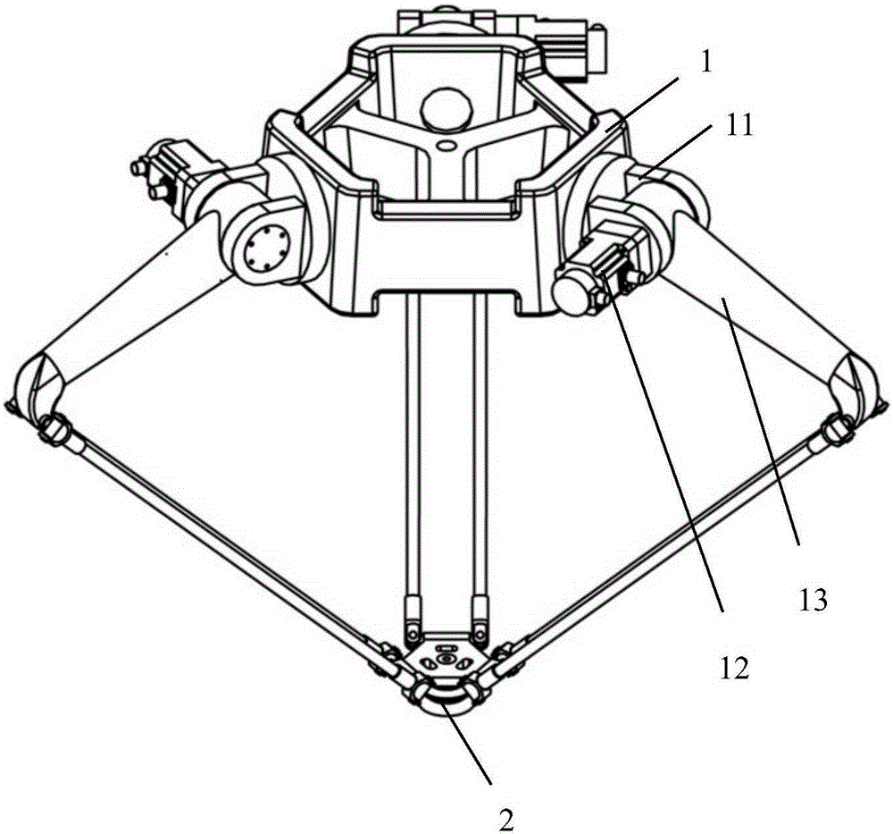
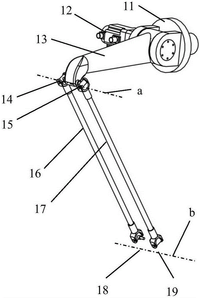
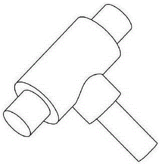
[0033] to combine Figure 1~3 , a three-translational parallel mechanism, including a fixed frame 1, a moving platform 2, and a first branch chain, a second branch chain and a third branch chain arranged between the fixed frame 1 and the moving platform 2; the first The branch chain, the second branch chain and the third branch chain have the same structure, and each branch chain includes a rotating fork 11, a driving device 12 fixedly arranged on the rotating fork 11, a driving arm 13, a first T-shaped shaft 14, a second T-shaped shaft 15, the first driven arm 16, the second driven arm 17, the third T-shaped shaft 18 and the fourth T-shaped shaft 19; One end of 13 is rotatably connected in the rotating fork 11, and is fixedly connected with the driving end of the driving device 12. One end of the T-shaped shaft 15 is rotatably connected, the other end of the first T-shaped shaft 14 is rotatably connected with one end of the first driven arm 16, and the other end of the first...

Embodiment 2

[0039] to combine Figure 4~6 , a three-translational parallel mechanism, including a fixed frame 1, a moving platform 2, and a first branch chain, a second branch chain and a third branch chain arranged between the fixed frame 1 and the moving platform 2; the first The branch chain, the second branch chain and the third branch chain have the same structure, and each branch chain includes a rotating fork 11, a driving device 12 fixedly arranged on the rotating fork 11, a driving arm 13, a first ball joint 14, a second ball joint Joint 15 , first follower arm 16 , second follower arm 17 , third ball joint 18 and fourth ball joint 19 . The rotating fork 11 is rotatably connected to the fixed frame 1, one end of the active arm 13 is rotatably connected in the rotating fork 11, and is fixedly connected to the driving end of the driving device 12, and the active arm 13 is far away from the driving device 12 The two sides of that end of the first follower arm 16 are fixedly connect...

Embodiment 3

[0044] This embodiment is similar to Embodiment 2, the only difference is that the active arm 13 and the first driven arm 16 are connected through the first T-shaped shaft 14, and the active arm 13 and the second driven arm 17 are connected through A second T-shaft 15 is connected.


PUM


Abstract

The invention discloses a three-transverse-movement parallel mechanism. The three-transverse-movement parallel mechanism comprises a fixed support, a movable platform and three branched chains arranged between the fixed support and the movable platform, wherein the branched chains are of the same structure; and each branched chain comprises a rotation fork, a driving arm, two parallel and equal-length driven arms and four T-shaped shafts, wherein each rotation fork is rotationally connected with the fixed support, and each driving arm is rotationally connected into the corresponding rotation fork; and one end of each driven arm is connected with the corresponding driving arm through two corresponding T-shaped shafts, and the other end of each driven arm is connected with the movable platform through two corresponding T-shaped shafts. By means of the parallel mechanism, over-constraining can be effectively eliminated, the structure is simple and compact, and the manufacturing cost is better reduced.

Description

technical field [0001] The invention relates to a parallel mechanism, in particular to a parallel mechanism with three-dimensional translation in space. Background technique [0002] The space three-translational parallel mechanism has been widely used in the high-speed and light-load handling operations of automated production lines in the fields of food, medicine, modern logistics, and electronic information because it can meet the handling operations of space objects. [0003] U.S. Patent No. 4,976,582 discloses a three-dimensional translation and one-dimensional rotation parallel mechanism, which includes three branch chains, and each branch chain includes two parts: a driving arm and a driven arm. There are two types of branch chains of this type of mechanism, one The main arm and the driven arm are both in the form of a single rod, and the two ends of the driven arm are respectively connected to the main arm and the moving platform through a Hooke hinge. The double-ro...

Claims


Application Information

Patent Timeline
Patent Type & Authority Applications(China)
IPC IPC(8): B25J9/00
Inventor 汪满新冯虎田欧屹
Owner NANJING UNIV OF SCI & TECH
Why Eureka
Try Eureka