
Support structure for supporting foundation pit and method for supporting foundation pit

A technology for supporting structures and foundation pits, applied in infrastructure engineering, excavation, construction, etc., can solve problems such as high cost, complex geological conditions, and slow construction speed, and achieve stable force system, low material cost, and small construction difficulty Effect

Active Publication Date: 2016-01-13
云南省水利水电工程有限公司
View PDF6 Cites 12 Cited by
  • Summary
  • Abstract
  • Description
  • Claims
  • Application Information

AI Technical Summary

Problems solved by technology

[0002] With the increase of urban population, more and more people begin to pay attention to the development of underground space, but the geological conditions of underground engineering are complicated, especially after excavation, a new excavation section is formed, which destroys the stability of the original structure of the rock mass. Safety accidents such as landslides and collapses are prone to occur during construction. In order to prevent the above-mentioned safety accidents, foundation pits need to be supported. For foundation pits with a design elevation within 15 meters, most of the current support methods use pile anchors for support. Anchor cables or anchor rods must be used for support at certain distances on the waist beam of cast-in-situ piles. The amount of anchor cables (anchor rods) used is large, the cost is high, the construction speed is slow, the efficiency is low, and the labor cost is high.

Method used


Image

  • Support structure for supporting foundation pit and method for supporting foundation pit

Examples


Embodiment Construction

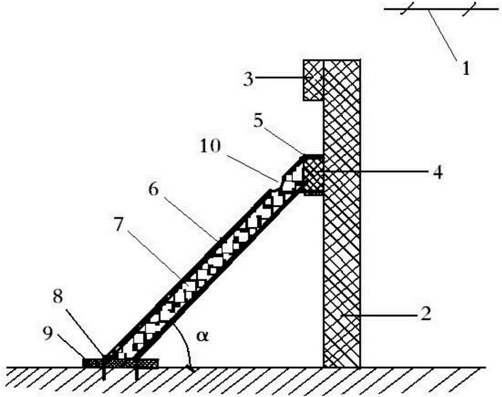
[0016] like figure 1 As shown, the support structure for supporting the foundation pit of the present invention includes cast-in-situ piles 2, crown beams 3 and waist beams 4 poured on the top and middle of the cast-in-place piles respectively, steel plates 5 pre-embedded on the waist beams, pre-embedded in the The embedded part 9 in the concrete cushion 9 at the bottom of the foundation pit, the inclined steel pipe 6 whose two ends are respectively welded on the steel plate and the embedded part, the grouting hole 10 opened on the upper part of the steel pipe and the grout 7 injected into the steel pipe. The diameter of the grouting hole 10 must not be greater than 1 / 3 of the diameter of the steel pipe 6, which is convenient for pouring grout and keeps the steel pipe strong enough. The angle α between the steel pipe 6 and the bottom surface of the foundation pit is 45°-60°.

[0017] The method of adopting the supporting structure of the present invention to support the found...


PUM


Abstract

The invention discloses a support structure for supporting a foundation pit and a method for supporting the foundation pit. The support structure comprises a bored pile (2), a top beam (3) and a breast beam (4) poured at the top and the middle of the bored pile respectively, a steel plate (5) pre-buried on the breast beam, an embedded part (8) pre-buried in a concrete cushion course (9) at the bottom of the foundation pit, an inclined steel pipe (6), a grouting hole (10) formed in the upper part of the steel pipe, and seriflux (7) filled in the steel pipe, wherein two ends of the inclined steel pipe (6) are welded on the steel plate and the embedded part respectively. According to the invention, the bored pile, the top beam, the breast beam and the steel pipe form a stress conversion system, and the pressure resistance and self weight of the seriflux, or concrete or gravel are fully utilized, so that a stress system is stable, safe and reliable, and can ensure safety of construction staff. The construction difficulty is small, the construction efficiency is high, and the material cost is low.

Description

technical field [0001] The invention relates to the technical field of foundation pit support in building construction. Background technique [0002] With the increase of urban population, more and more people begin to pay attention to the development of underground space, but the geological conditions of underground engineering are complicated, especially after excavation, a new excavation section is formed, which destroys the stability of the original structure of the rock mass. Safety accidents such as landslides and collapses are prone to occur during construction. In order to prevent the above-mentioned safety accidents, foundation pits need to be supported. For foundation pits with a design elevation within 15 meters, most of the current support methods use pile anchors for support. For protection, anchor cables or anchor rods must be used for support at certain distances on the waist beam of cast-in-situ piles. The amount of anchor cables (anchor rods) used is large, ...

Claims


Application Information

Patent Timeline
IPC IPC(8): E02D17/04
Inventor 雷春燕沈家文王剑非王晓燕周麟杨成王建成张恩超魏聪明
Owner 云南省水利水电工程有限公司
Learn More