
Locomotive test differential gear case and test table

A gear box, test bench technology, applied in the direction of differential transmission, belt/chain/gear, mechanical equipment, etc., can solve problems such as inability to meet

Active Publication Date: 2016-01-13
CHONGQING ZHIZHAN GEAR TRANSMISSION
View PDF4 Cites 2 Cited by
  • Summary
  • Abstract
  • Description
  • Claims
  • Application Information

AI Technical Summary

Problems solved by technology

However, none of the above three differentials can meet the requirements of 1:1 synchronous speed when the locomotive is running, and the function of active differential when driving on a curve.

Method used


Image

  • Locomotive test differential gear case and test table

Examples


Embodiment Construction

[0023] The core of the present invention is to provide a differential gearbox for locomotive testing. The device is used for locomotive testing and can meet the requirements of both straight line testing and curve testing. In addition, another core of the present invention is to provide a locomotive test bench including a locomotive test differential gearbox.

[0024] In order to enable those skilled in the art to better understand the technical solution provided by the present invention, the locomotive test differential gearbox provided by the present invention will be described in detail below in conjunction with the drawings and specific embodiments.

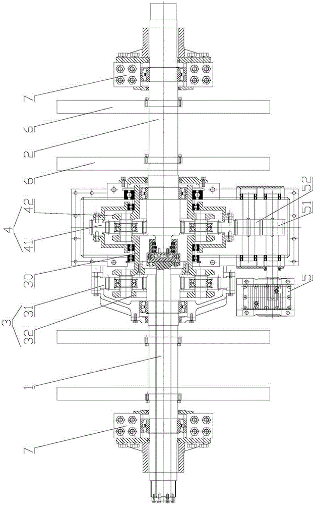
[0025] Such as figure 1 Shown is a schematic cross-sectional structure diagram of the locomotive test differential gearbox provided by the present invention. The differential gear box designed in the present invention specifically includes an input shaft 1 and an output shaft 2, both of which are located on the same straight...


PUM


Abstract

The invention discloses a locomotive test differential gear case. The locomotive test differential gear case comprises an input shaft, an output shaft, a first planet gear set, a second planet gear set and a speed regulation motor. The input shaft and the output shaft are arranged on the same straight line. The input shaft and the output shaft are rotationally connected. The first planet gear set is arranged on the input shaft in a sleeving manner and used for decreasing speed. The second planet gear set is arranged on the output shaft in a sleeving manner and used for increasing speed. The first planet gear set and the second planet gear set are meshed, and the gear ratios of all stages of the first planet gear set are the same as the gear ratios of all stages of the second planet gear set. The speed regulation motor is arranged on the outer side of a second inner gear ring in the second planet gear set in a meshed manner. When a linear driving test is performed, the speed of the input shaft is decreased through the first planet gear set, the speed of the input shaft is increased through the second gear set, and the condition that the linear driving rotation speed ratio is 1:1 is met. When a bend test is performed, the speed regulation motor is started, and the second inner gear ring is driven to rotate, so that the rotation speed of the output shaft and the rotation speed of the input shaft are in certain proportion under the stacking effect, and the differential ratio needed by the bend test is achieved. A locomotive test table can achieve the effect achieved by the gear case.

Description

technical field [0001] The invention relates to the technical field of locomotive testing, in particular to a differential gear box for locomotive testing. Furthermore, the invention also relates to a locomotive test stand. Background technique [0002] Differentials are required for locomotive testing. At present, traditional differentials are mainly divided into three types: NGW differentials, WW differentials and bevel gear differentials. NGW differentials are active differentials. The speed ratio is 3.5-5.5, and the inner ring gear is driven by the speed regulating motor to realize speed regulation; the WW differential is an active differential, and the differential speed ratio is 1.8-3, and the speed regulation is realized by driving the planet carrier to rotate through the speed regulating motor The bevel gear differential is a passive differential with a differential ratio of 1-2. The differential function is automatically realized through the change of the torque tr...

Claims


Application Information

Patent Timeline
Patent Type & Authority Applications(China)
IPC IPC(8): F16H48/06
CPCF16H48/06
Inventor 江师露周宏张军楷石燕玲
Owner CHONGQING ZHIZHAN GEAR TRANSMISSION
Learn More