Control rod drive wire displacement compensation device, forming mold and forming method of control rod drive wire displacement compensation device

A technology for displacement compensation and forming molds, which is applied to expansion compensation devices for pipelines, pipes/pipe joints/pipes, mechanical equipment, etc., and can solve the problems of inability to perform three-dimensional displacement at the same time, complex bellows structure, and large volume. Achieve the effect of improving displacement compensation ability and anti-fatigue performance, improving anti-expansion and bending fatigue performance, and requiring low installation accuracy

Active Publication Date: 2016-01-13
AEROSUN CORP
View PDF6 Cites 11 Cited by
  • Summary
  • Abstract
  • Description
  • Claims
  • Application Information

AI Technical Summary

Problems solved by technology

However, at present, the bellows as a displacement compensator has a complex structure, and usually can only perform lateral or axial compensation, and cannot simultaneously compensate three-dimensional displacements, and its volume is huge, which cannot meet the needs of displacement compensation in a narrow space

Method used


Image

  • Control rod drive wire displacement compensation device, forming mold and forming method of control rod drive wire displacement compensation device
  • Control rod drive wire displacement compensation device, forming mold and forming method of control rod drive wire displacement compensation device
  • Control rod drive wire displacement compensation device, forming mold and forming method of control rod drive wire displacement compensation device

Examples


Embodiment 1

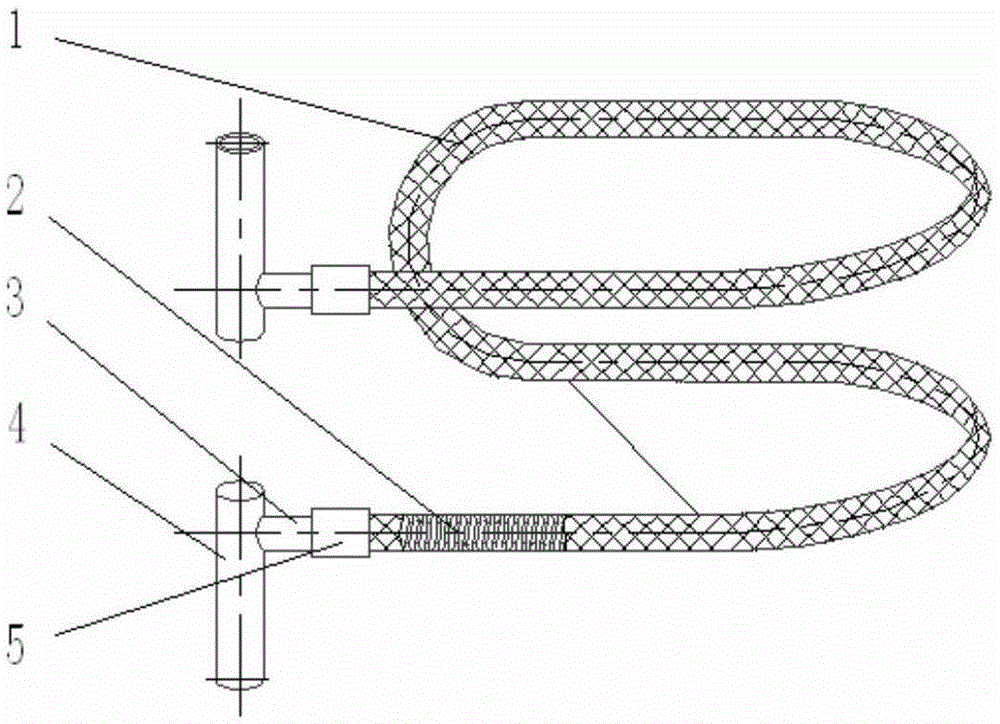
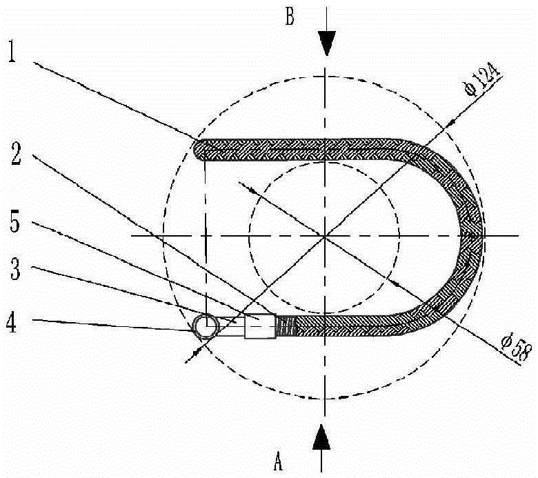
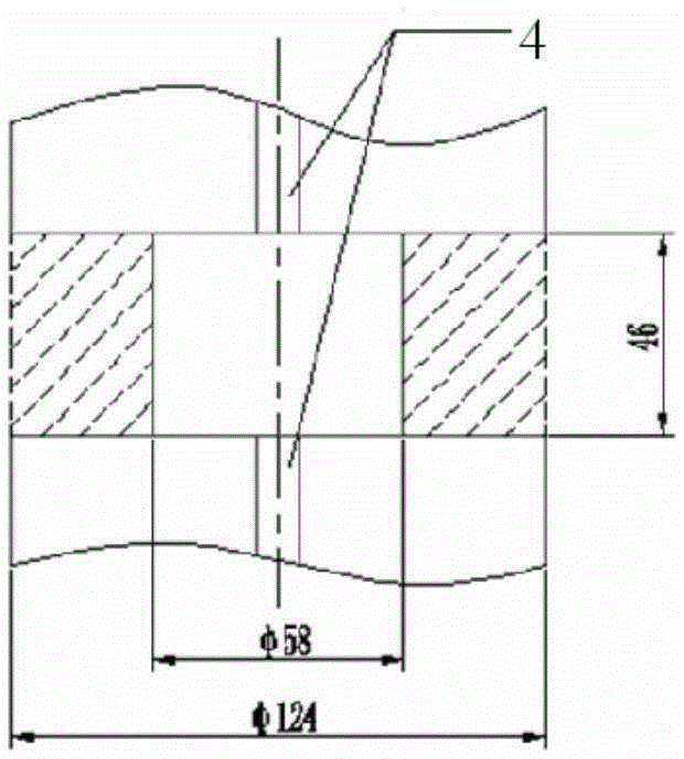
[0045] A control rod drive line displacement compensation device of this embodiment, such as Figure 1-6 As shown, it is installed in a circular column space with an outer diameter of φ124mm, an inner diameter of φ58mm, and a height of 46mm. It includes a metal corrugated pipe 2 and a steel mesh sleeve 1 and a metal corrugated pipe 2 wrapped around the metal corrugated pipe 2. The two ends of the metal bellows are respectively connected to the vertical ferrule joint 4 through seamless joints, and the two ends of the metal bellows 2 respectively extend from the corresponding seamless joints 3 in the horizontal direction, and are bent by a vertical semicircular arc to form a vertical U-shaped bends 2-1, 2-3; and then align with each other through horizontal semi-circular arc bending to form a horizontal U-shaped bend 2-2; the ferrule joint 4 is welded to the control rod pipeline. The position and direction of the ferrule joint 4 are allowed to have a certain amount of deviation, w...

Embodiment 2

[0070] This embodiment provides a control rod drive line displacement compensation device, such as Figure 7-9 As shown, among the three continuous curved shapes of the metal bellows in the control rod drive line displacement compensation device of this embodiment, the second curved shape 2-4 is an Ω shape. The other structure, forming mold, and heating method are basically the same as those of the first embodiment. It is installed in a circular column space with an outer diameter of φ150mm, an inner diameter of φ60mm, and a height of 50mm.

[0071] The second curved Ω-shaped bend is composed of a 210°~240° big arc and two 15°~30° small arcs connected to the two ends of the arc. The bending radius of the small arcs at both ends is larger than the center of the big circle. 1.5 times the angle arc, because the Ω-shaped bend has a longer arc segment with a large central angle under the same bending radius, the compensation device with the Ω-shaped bend has a larger compensation dis...


PUM


Abstract

The invention discloses a control rod drive wire displacement compensation device which comprises a metal corrugated pipe and a mesh cover wrapping the metal corrugated pipe. The two ends of the metal corrugated pipe are connected with connectors through connecting pipes respectively, and the connectors are perpendicular to the two ends of the metal corrugated pipe. The two ends of the metal corrugated pipe extend in parallel in the horizontal direction from the corresponding connecting pipes and then are bent to form a vertical U-shaped bend through vertical semi-arc bends and oppositely closed to form a horizontal bend through horizontal arcs. The vertical U-shaped bend is organically combined with the horizontal arc bend, and therefore compensation of displacement in the three-dimensional direction can be achieved, the corrugated structure is combined with the deformation degree of the U-shaped bend, so that the displacement compensation capacity is obviously improved, and the telescopic resistance and flexural fatigue performance are greatly improved; and therefore the service life of the displacement compensation device exceeds millions of times, and is obviously longer than that of an existing displacement compensation device. Meanwhile, the structure can be mounted in narrow space such as an annular column, the requirement for mounting precision is low, enough inner pressure and outer pressure resisting capacity is achieved, and medium leakage cannot happen within the life period.

Description

technical field [0001] The invention relates to a displacement compensation device for a control rod driving line, a forming die and a forming method thereof, and belongs to the technical field of flexible connecting pipes for conveying pipelines. Background technique [0002] To the applicant's knowledge, some nuclear reactor control rod drive lines consist of a series of electromechanical hydraulic systems. When it works, the transmission shaft and the control rod bundle move step by step, resulting in relative displacement between the hydraulic transmission components in the control rod, so a device is required to compensate for the displacement while delivering the hydraulic medium. Limited by the structure of the control rods, the installation space of the compensation device is extremely small, and it is required to have sufficient resistance to positive and negative pressures. In order to ensure the long-term operation of the control rod drive line, the displacement ...

Claims


Application Information

Patent Timeline
Patent Type & Authority Applications(China)
IPC IPC(8): F16L51/02
CPCF16L51/02
Inventor 范荣超张华京郭志承梅鑫翟明智
Owner AEROSUN CORP
Why Eureka
Try Eureka