Combined special-shaped diaphragm flexible shaft coupling

A flexible coupling and composite technology, applied in elastic couplings, couplings, mechanical equipment, etc., can solve the problem of insufficient displacement compensation capacity of couplings, difficult coupling design work, and shutdown of complete sets of equipment. Accidents and other problems, to achieve the effect of improving the comprehensive transmission capacity, relieving the bending stress burden, and the large axial free expansion and contraction capacity

Inactive Publication Date: 2008-05-14
SUZHOU FL COUPLING DRIVE ENG
View PDF0 Cites 10 Cited by
  • Summary
  • Abstract
  • Description
  • Claims
  • Application Information

AI Technical Summary

Problems solved by technology

[0015] The contradictory results are: either the bearing capacity is insufficient, and the coupling itself fails prematurely; or the displacement compensation capacity of the coupling is insufficient, resulting in frequent production shutdown accidents of "burning tiles" in complete sets of equipment
There is such a sharp contradiction between the compensation capacity and the carrying capacity of the traditional diaphragm coupling, which makes the design of the coupling difficult and helpless

Method used


Image

  • Combined special-shaped diaphragm flexible shaft coupling
  • Combined special-shaped diaphragm flexible shaft coupling
  • Combined special-shaped diaphragm flexible shaft coupling

Examples


Embodiment

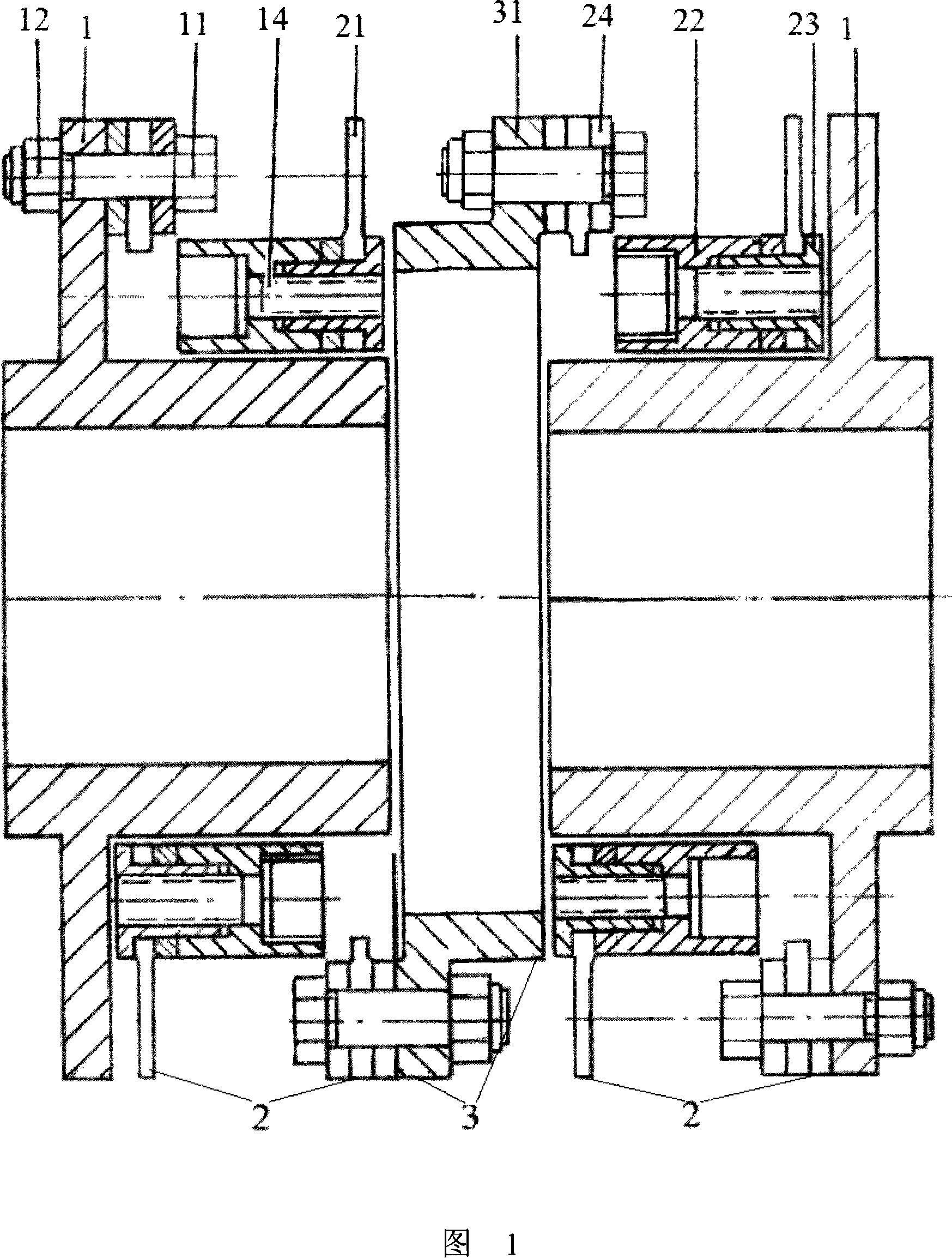
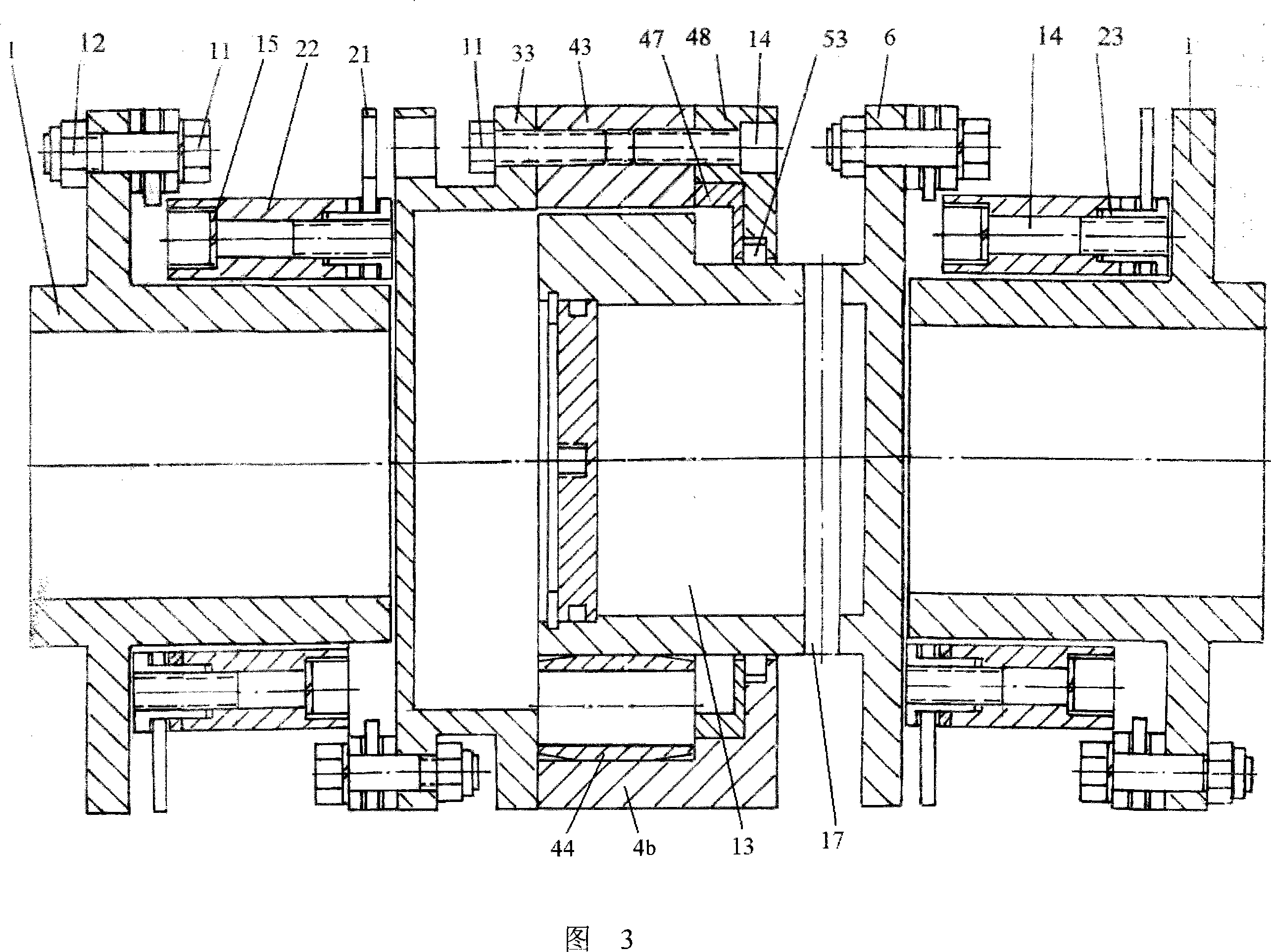
[0063] Embodiment: As shown in Figures 1 to 16, a composite special-shaped diaphragm flexible coupling includes flanges 1 at both ends, diaphragm assemblies 2 and spacers 3 connected between adjacent diaphragm assemblies 2 , the outer ends of the outermost two diaphragm assemblies 2 are connected to the inner end of the flange 1, the coupling has at least two diaphragm assemblies 2, and the diaphragm assembly 2 includes two diaphragm segments 21 and placed Synchronizing ring 22 between two diaphragm segments 21 .

[0064] The diaphragm section 21 includes a plurality of three-hole strip-shaped laminated diaphragm units 211, and the adjacent three-hole strip-shaped laminated diaphragm units 211 are closely connected from end to end. On the three-hole strip-shaped laminated diaphragm units 211 There is an inner ring hole at the center and two outer ring holes at both ends.

[0065] The membrane section 21 is a single porous annular laminated membrane unit 212, and the porous an...

Embodiment 1

[0074]As shown in Figure 1, a composite special-shaped diaphragm flexible coupling includes two flanges 1, two diaphragm assemblies 2 connected to the two flanges 1, and the gap between the two diaphragm assemblies 2. Connected spacer segment 3. The composite special-shaped diaphragm flexible coupling has two diaphragm assemblies 2, each diaphragm assembly 2 includes two diaphragm segments 21 and a synchronizing ring 22 placed between the two diaphragm segments 21; The membrane section 21 includes a plurality of three-hole strip-shaped laminated membrane units 211 (see FIG. 8 ). A lotus-leaf-shaped spacer 31 is sandwiched between the two diaphragm assemblies 2 , the shaft of the flange is set toward the inside, and the synchronous ring 22 of the diaphragm assembly 2 is directly sleeved outside the shaft sleeve of the flange.

[0075] The advantage of this embodiment is that the axial dimension of the coupling is even smaller than the outer diameter of the coupling; the coupli...

Embodiment 2

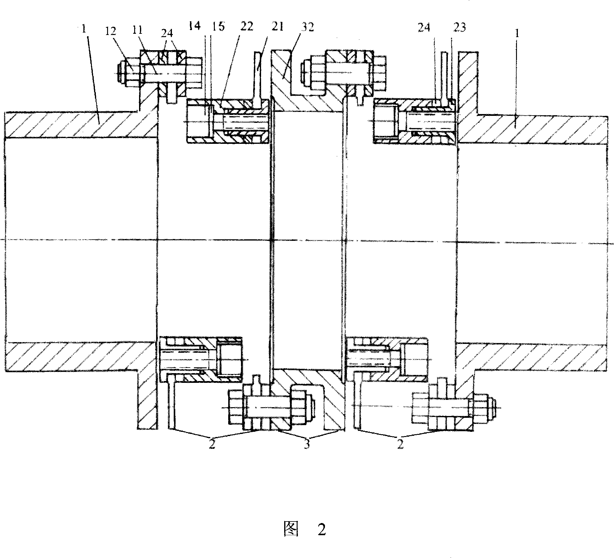
[0077] As shown in Figure 2, a composite special-shaped diaphragm flexible coupling includes two flanges 1, two diaphragm assemblies 2 connected to the two flanges 1, and the gap between the two diaphragm assemblies 2. For the connected spacer section 3 , the end face of the flange 1 is correspondingly connected with the end face of the diaphragm assembly 2 , and the spacer section 3 is a spacer plate 32 with a Π-shaped cross section. The composite special-shaped diaphragm flexible coupling has two diaphragm assemblies 2, each diaphragm assembly 2 includes two diaphragm segments 21 and a synchronizing ring 22 placed between the two diaphragm segments 21; The membrane section 21 can be a plurality of three-hole strip-shaped laminated membrane units 211 or a porous ring-shaped laminated membrane unit 212 .

[0078] This embodiment is suitable for equipment that has strict control requirements on the radial dimension of the coupling and allows the coupling to have a relatively lo...


PUM


Abstract

The invention discloses a composite abnormal membrane flexible coupler, comprising a flange at the end part, and a membrane combination piled by bar-shaped membranes; an interval section is connected between two adjacent membranes; the coupler is provided with at least two membrane combinations; the membrane combination comprises two membrane joints and a synchronous ring between two membrane joints; the interval section can be a simple interval disc, a spline flexible interval device, or a combined elastic spline flexible damping interval device; the invention has the advantages of extremely compact structure on the conditions of middle and low speed and heavy load, extremely great bearing capability, extremely great axial, angle and radial displacement compensation, full and advanced comprehensive transmission capability, free assembly without obstacle on site, extremely convenient disassembly, and high economics.

Description

technical field [0001] The invention relates to a composite special-shaped diaphragm flexible shaft coupling. Background technique [0002] The mission of the flexible coupling is to transmit the torque of the prime mover to the driven machine while compensating the axis misalignment between the shaft of the prime mover and the shaft of the driven machine due to manufacturing errors, installation errors, bearing deformation, thermal deformation, etc. Medium offset. [0003] The "comprehensive transmission capacity" of the flexible coupling not only includes the basic "carrying capacity" required to transmit torque, but also must include the "displacement compensation" caused by the corresponding "displacement compensation" of the laminated diaphragm rod due to the misalignment of the equipment axis. additional bending stress. For field work equipment such as aircraft, boats, vehicle-mounted equipment, or equipment with harsh working conditions, the additional bending stres...

Claims


Application Information

Patent Timeline
Patent Type & Authority Applications(China)
IPC IPC(8): F16D3/56
Inventor 黄天梵
Owner SUZHOU FL COUPLING DRIVE ENG
Why Eureka
Try Eureka