Switching arrangement

A switch and switching device technology, applied in electrical switches, protection switches, parts of protection switches, etc., can solve the problems of unreliability, no longer reliable, and the influence of switch layout, and achieve the effect of simple adjustment and simplified operation

Active Publication Date: 2016-01-13
TE CONNECTIVITY GERMANY GMBH
View PDF5 Cites 17 Cited by
  • Summary
  • Abstract
  • Description
  • Claims
  • Application Information

AI Technical Summary

Problems solved by technology

However, this is unreliable, since parts of the microswitch can be damaged and thus have an effect on the switch arrangement such that it no longer functions reliably
Also, this solution is usually not allowed, because under certain circumstances high voltage may exist on the micro switch

Method used


Image

  • Switching arrangement
  • Switching arrangement
  • Switching arrangement

Examples


Embodiment Construction

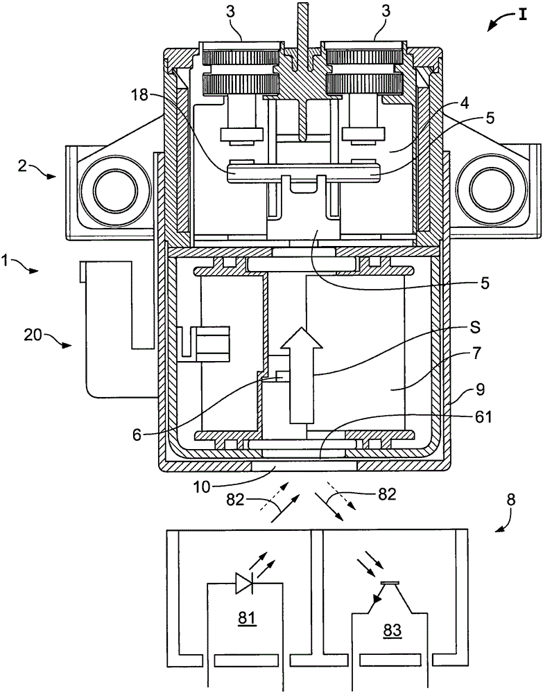
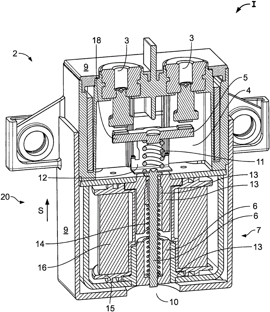
[0042] switch arrangement 1 in figure 1 shown in . The switch arrangement 1 comprises a switch 2 with two contacts 3 which are arranged in a contact switch chamber 4 . The switching device 5 is used to establish or break an electrical connection between two contacts 3 . For this purpose, the switching device 5 can be used as figure 1 The shown movement is between a disconnected position I, in which the contacts 3 are electrically separated from each other, and a bridging position, in which the contacts 3 are electrically conductively connected to each other by means of the switching device 5 .

[0043] The switching device 5 comprises a contact bridge 18 and an armature 6 . The armature 6 is arranged in a coil 7 which, for the sake of illustration of other elements, is in figure 1 is shown as partially excised. Depending on whether, with what strength and in which direction the current flows in the coil, the armature 6 and thus the switching device 5 moves in or against t...


PUM


Abstract

The invention relates to a switching arrangement (1), in particular for the high-voltage and / or high-current region, with two contacts (3) and a switching device (5), which can be moved into a separated position (I) in which the contacts (3) are electrically separated from one another. The object of the invention is to provide a solution with which it is possible to easily and reliably ascertain whether the switching arrangement (1) is insulated. According to the invention, this is achieved in that the presence of the switching device (5) in the separated position (I) is detected by a contact-free measurement of the position of the switching device (5). A switching arrangement (1) according to the invention comprises a detector (8) with which the presence of the switching device (5) in the separated position (I) can be detected in a contact-free manner.

Description

technical field [0001] The invention relates to a switch arrangement, or a switch assembly, especially for use in high voltage and / or high current areas, with two contacts and a switching device movable into a disengaged position, the In the separated position the contacts are electrically separated from each other. Background technique [0002] Such switch arrangements are used, for example, in electric vehicles. In order to ensure that, for example, no dangerous voltages arise in the case of maintenance work, it is necessary to be able to detect that the switching arrangement is sufficiently insulated. [0003] In the case of the past method, the measurement is thereby performed directly in the circuit. In this condition, auxiliary relays are used to couple the measuring equipment to the circuit. However, this is complicated. [0004] In the case of a different past method, the position of the switching device is sensed by a microswitch. However, this is unreliable, s...

Claims


Application Information

Patent Timeline
Patent Type & Authority Applications(China)
IPC IPC(8): H01H9/16H01H50/08G01R31/327
CPCG01R31/3271H01H9/16H01H50/08H01H1/0015H01H1/20H01H71/04H01H2071/048G01S17/06H01F7/1844
Inventor H·科克M·克罗克C·林德纳
Owner TE CONNECTIVITY GERMANY GMBH
Why Eureka
Try Eureka