
35kv post insulator intermediate phase automatic wire supporting device

A post insulator, automatic technology, applied in the direction of overhead line/cable equipment, etc., can solve the problems of inconvenient use, falling of high-altitude workers, wear and tear of wires, etc., and achieve the effect of convenient adjustment, improved safety and high work efficiency

Inactive Publication Date: 2016-01-13
梁永超
View PDF6 Cites 0 Cited by
  • Summary
  • Abstract
  • Description
  • Claims
  • Application Information

AI Technical Summary

Problems solved by technology

However, the 35kV transmission line is located in hilly and mountainous areas, with large spans, and inclement weather is prone to breakage of insulators and wire shedding, which affects the safety and stable operation of the line.
Once the middle phase insulator is damaged and needs to be replaced, it will be difficult to lift the wire and restore it to its original position
In the process of replacing insulators, if the gear distance is too large, it is impossible for a single person to complete the wire homing operation; if relying on the shoulders of workers at heights to support the wires, it will greatly consume their physical strength, and it is easy to cause the wires to slip from the shoulders to the cross arm, which can easily cause the wires to be damaged. Wear and tear; and high-altitude workers are susceptible to falling from high altitudes due to wire slippage, which is very dangerous
Moreover, the existing automatic wire support device cannot be fine-tuned during use, resulting in inconvenient use and a waste of time

Method used


Image

  • 35kv post insulator intermediate phase automatic wire supporting device
  • 35kv post insulator intermediate phase automatic wire supporting device

Examples


Embodiment Construction

[0012] Below in conjunction with accompanying drawing, the present invention will be further described.

[0013] In order to make the object, technical solution and advantages of the present invention clearer, the present invention will be further described in detail below in conjunction with the accompanying drawings and specific embodiments. It should be understood that the specific embodiments described here are only used to explain the present invention, and are not intended to limit the present invention.

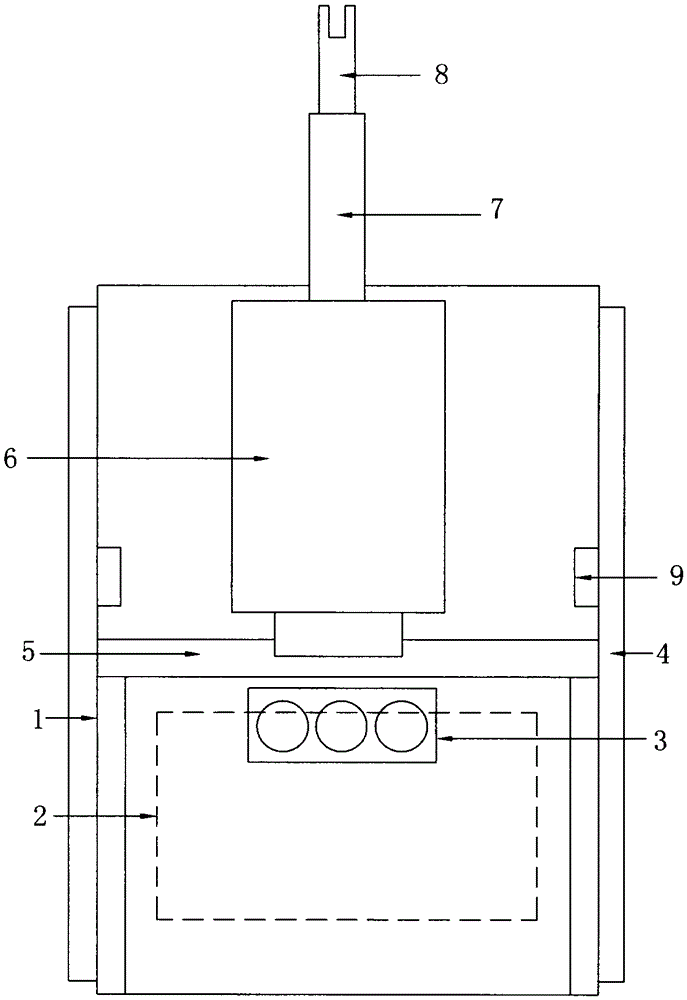
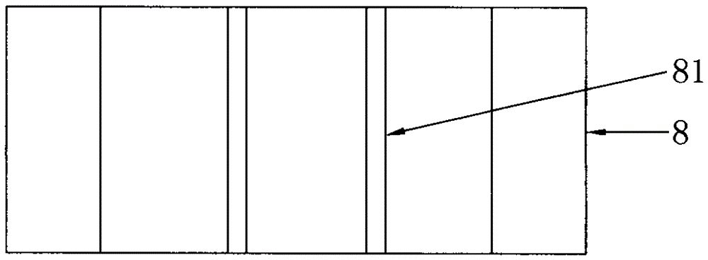
[0014] Such as Figure 1-2 As shown, this specific embodiment adopts the following technical scheme: it includes a power control box 1, a power supply unit 2, a status display unit 3, a hoop 4, an electric slide rail mechanism 5, a lifting mechanism 6, a connecting rod 7, a fixed bracket 8, Limit switch 9; hoop 4 is installed at the rear end of power control box 1, power supply unit 2 is installed inside power control box 1, status display unit 3 is installed on the o...


PUM


Abstract

The invention discloses a 35kV post insulator intermediate phase automatic wire supporting device, relating to the technical field of power production and maintenance. A state display unit is installed on the outer surface of a power control box, an electric slide rail mechanism is installed in the middle of the interior of the power control box, a lifting mechanism is installed on a slide block of the electric slide rail mechanism, a lifting rod of the lifting mechanism is connected with a fixed support through a connecting rod, a wire fixing slot is formed in the fixed support, and two limit switches are respectively installed on the side walls of the power control box; a power supply unit supplies power to the lifting mechanism to control the lifting mechanism to propel lifting of the fixed support, meanwhile, the electric slide rail mechanism drives the fixed support to realize fine adjustment, and the support can be raised to lift a conducting wire during maintenance; after the maintenance, the support can descend to lower the conducting wire; the state display unit can display the motion state of the lifting mechanism; and the device can conveniently support the conducting wire, is convenient and fast in adjustment and high in working efficiency, and improves the safety.

Description

Technical field: [0001] The invention relates to the technical field of electric power production and maintenance, in particular to a mid-phase automatic wire support device for 35kV post insulators. Background technique: [0002] In the 35kV old-fashioned lines, the conductors are usually arranged in a triangular arrangement. In order to save cost, improve the safe and reliable operation of power transmission and equipment, porcelain cross arm is used. However, the 35kV transmission lines are located in hilly and mountainous areas with large spans, and inclement weather is prone to breakage of insulators and wire shedding, which affects the safe and stable operation of the line. Once the middle phase insulator is damaged and needs to be replaced, it will be difficult to lift the wire and restore it to its original position. In the process of replacing insulators, if the gear distance is too large, a single person cannot complete the wire homing operation; if relying on th...

Claims


Application Information

Patent Timeline
Patent Type & Authority Applications(China)
IPC IPC(8): H02G1/02
Inventor 梁永超荣禧杨洪双于涛刘国勇
Owner 梁永超
Learn More