Visual measurement method for dynamic error of five-axis CNC machine tool
A technology of CNC machine tools and visual measurement, which is used in measurement/indication equipment, metal processing machinery parts, metal processing equipment, etc.
- Summary
- Abstract
- Description
- Claims
- Application Information
AI Technical Summary
Problems solved by technology
Method used
Image
Examples
Embodiment Construction
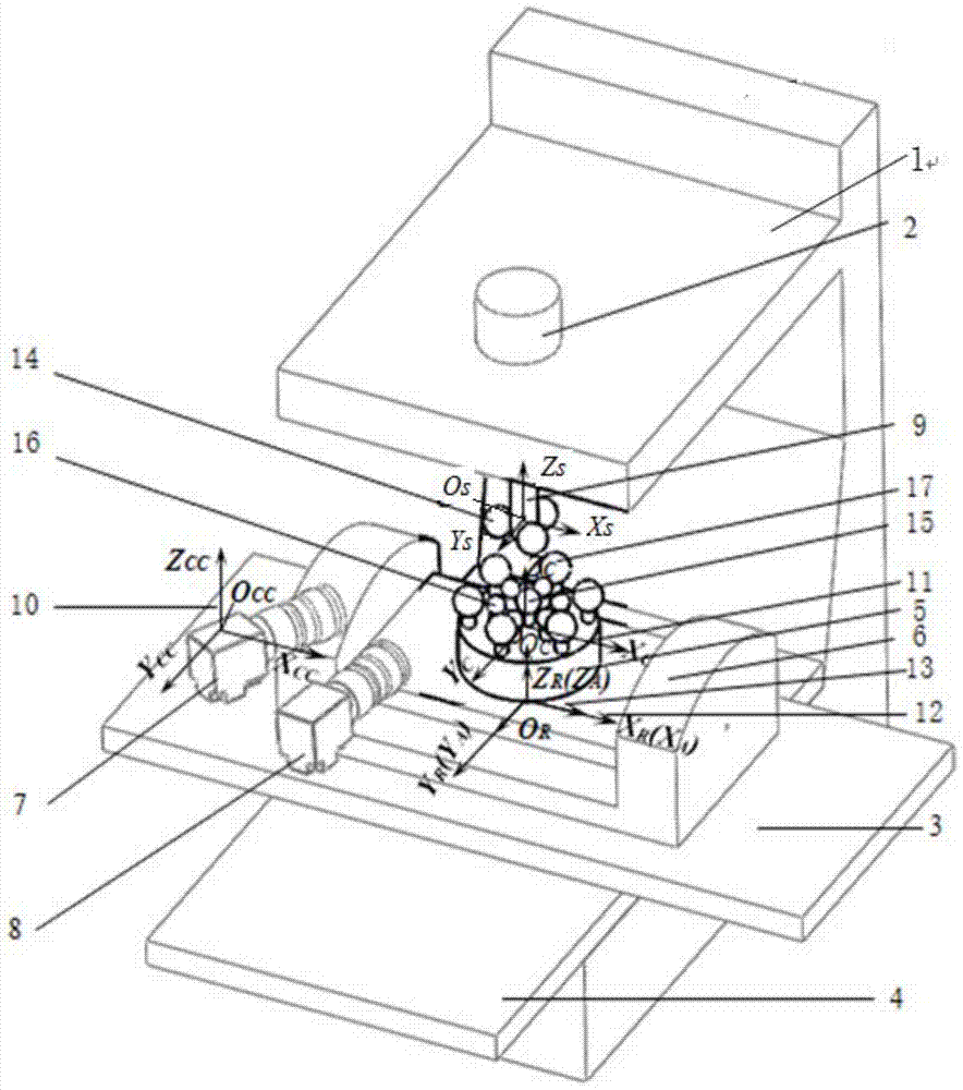
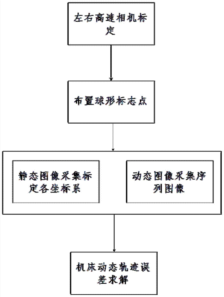
[0039] The following combined technical solutions and attached figure 1 and 2 Specific embodiments of the present invention will be described in detail.
[0040] attached figure 1It is a schematic diagram of the visual measurement of the high-speed dynamic space trajectory error of the five-axis linkage CNC machine tool. The moving parts on the five-axis CNC machine tool 1 are composed of a machine tool spindle part 2, a machine tool X-axis part 3, a machine tool Y-axis part 4, a machine tool C-axis part 5, and a machine tool A-axis part 6; the machine tool spindle part 2 is a moving part , located on the Z-axis of the machine tool; the X-axis part 3 of the machine tool and the Y-axis part 4 of the machine tool constitute the workpiece table of the machine tool as moving parts; the installation sequence from the bottom to the top of the machine bed is Y-axis part 4 of the machine tool, X-axis part 3 of the machine tool, and A-axis component 6, machine tool C-axis component ...
PUM
 Abstract
Description
Claims
Application Information
 - R&D
- Intellectual Property
- Life Sciences
- Materials
- Tech Scout
- Unparalleled Data Quality
- Higher Quality Content
- 60% Fewer Hallucinations
Browse by: Latest US Patents, China's latest patents, Technical Efficacy Thesaurus, Application Domain, Technology Topic, Popular Technical Reports.
© 2025 PatSnap. All rights reserved.Legal|Privacy policy|Modern Slavery Act Transparency Statement|Sitemap|About US| Contact US: help@patsnap.com


