GNSS (Global Navigation Satellite System) sea surface geodetic height surveying buoy

A technology of high ground and buoys, which is applied in the direction of buoys, special-purpose ships, ships, etc., can solve the problems of severe shaking, reinitialization of cycle slips, large antenna height errors, etc., to improve data collection quality, improve attitude stability, The effect of ensuring stability

Inactive Publication Date: 2016-01-20
STATE OCEAN TECH CENT
View PDF9 Cites 6 Cited by
  • Summary
  • Abstract
  • Description
  • Claims
  • Application Information

AI Technical Summary

Problems solved by technology

[0005] Among them, the GNSS antenna is installed on a simple floating body such as a life buoy. The structure of the floating body is a single floating body with a small volume. The GNSS antenna is usually close to the sea level and is easily affected by complex conditions such as waves and currents in harsh sea conditions, causing GNSS signals The lock is lost, and a large number of stray signals reflected by the sea surface enter the antenna, resulting in serious multipath effects; while the spherical, cylindrical, barrel-shaped and other single-buoy buoys are not specially designed for attitude stability. Severe shaking under complex conditions such as ocean currents can easily cause the GNSS signal to lose lock, and cause a large number of stray signals reflected by the sea surface to enter the antenna, causing serious multipath effect

Method used


Image

  • GNSS (Global Navigation Satellite System) sea surface geodetic height surveying buoy
  • GNSS (Global Navigation Satellite System) sea surface geodetic height surveying buoy
  • GNSS (Global Navigation Satellite System) sea surface geodetic height surveying buoy

Examples


Embodiment Construction

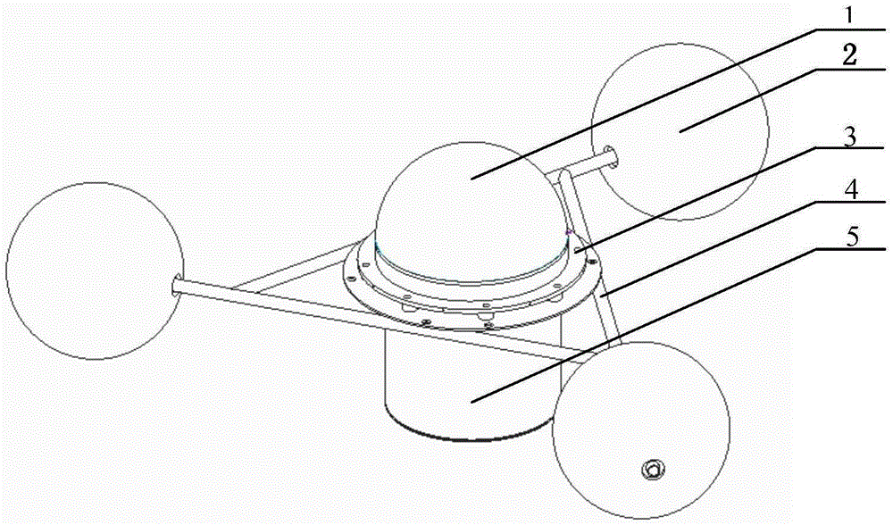
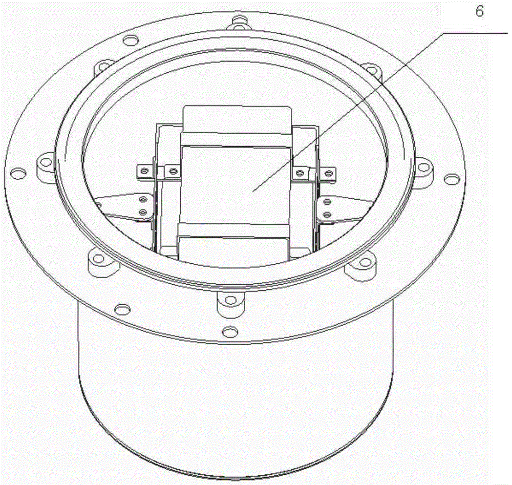
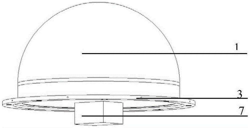
[0026] The technical solution of the present invention is further described in conjunction with the accompanying drawings, figure 1 showing the basic structure of the present invention, figure 2 and image 3 Shows the basic structure of its instrument compartment and instrument hatch cover. As shown in the figure, the GNSS sea surface geodetic buoy involved in the present invention includes a tripod 4 , a buoy 2 , a GNSS antenna and an instrument cabin 5 . The instrument cabin 5 is located at the center of the tripod 4, the tripod 4 is connected to the floating ball 2, the GNSS antenna is fixed on the airtight hatch 3 at the top of the instrument cabin 5, and the radome 1 is directly fixed on the GNSS antenna by screws.

[0027] The GNSS antenna adopts a choke coil antenna and is fixed on the airtight hatch 3 on the upper part of the instrument cabin 5 . The GNSS antenna is connected with the GNSS receiver 6 in the instrument cabin 5 through a coaxial cable.

[0028] The ...


PUM


Abstract

The invention discloses a GNSS (Global Navigation Satellite System) sea surface geodetic height surveying buoy, comprising an A-frame, a floating ball, a GNSS antenna and an instrument cabin, wherein the instrument cabin is located at the center of the A-frame, the A-frame is connected with the floating ball, the GNSS antenna is fixed on a sealed hatch on the upper part of the instrument cabin, and an antenna cover is mounted on the GNSS antenna; the floating ball is a solid and light ball body, the center of the floating ball is provided with a through round hole, a support rod extended from a vertex angle of the A-frame penetrates through the round hole in the center of the floating ball, and the floating ball is fixed on the support rod of the A-frame; the instrument cabin is fixed on the A-frame, the top surface of the instrument cabin is provided with the sealed hatch, and a power supply, a GNSS receiver and an attitude sensor are arranged in the instrument cabin; the GNSS antenna adopts a choking coil antenna, and is connected with the GNSS receiver in the instrument cabin by a coaxial cable; a GNSS base station is utilized to perform dynamic relative positioning on the GNSS buoy, and an accurate sea surface geodetic height is acquired according to the height and the attitude of the antenna of the buoy.

Description

technical field [0001] The invention relates to a marine measuring instrument, in particular to a sea surface geodetic height measuring buoy used for altimeter sea surface height calibration. Background technique [0002] In the past 20 years, satellite altimeters have made great contributions to ocean research with their high precision and high performance, and have been widely used in ocean dynamic environment observations, such as ocean circulation, ocean tides, mesoscale eddies, upwelling, Applications of fronts and geoids and gravity anomalies. In order to ensure the accuracy of the altimeter measurement, it is necessary to perform absolute deviation calibration and long-term drift calibration on the altimeter observation results. [0003] The altimeter calibration is mainly to compare the geodetic height measured at the sub-satellite point on site with the sea level data of the altimeter, and calculate the deviation and drift between the two. Usually, GNSS (Global Na...

Claims


Application Information

Patent Timeline
IPC IPC(8): B63B22/24
Inventor 闫龙浩朱建华陈春涛张晓旭张倩翟万林
Owner STATE OCEAN TECH CENT
Why Eureka
Try Eureka