
Machine jellyfish driven by embedded type cylindrical motor

A motor-driven, embedded technology, applied in ship propulsion, ship parts, ships, etc., can solve the problems of small effective water spray volume, limited movement range, and inapplicability

Active Publication Date: 2014-11-19
HARBIN INST OF TECH
View PDF6 Cites 22 Cited by
  • Summary
  • Abstract
  • Description
  • Claims
  • Application Information

AI Technical Summary

Problems solved by technology

[0006] The purpose of the present invention is to solve the problems that existing bionic jellyfish robots have limited range of motion, small effective water spray volume, small driving force, and are not suitable for complex water flow environments in nature.

Method used


Image

  • Machine jellyfish driven by embedded type cylindrical motor
  • Machine jellyfish driven by embedded type cylindrical motor
  • Machine jellyfish driven by embedded type cylindrical motor

Examples


specific Embodiment approach 1

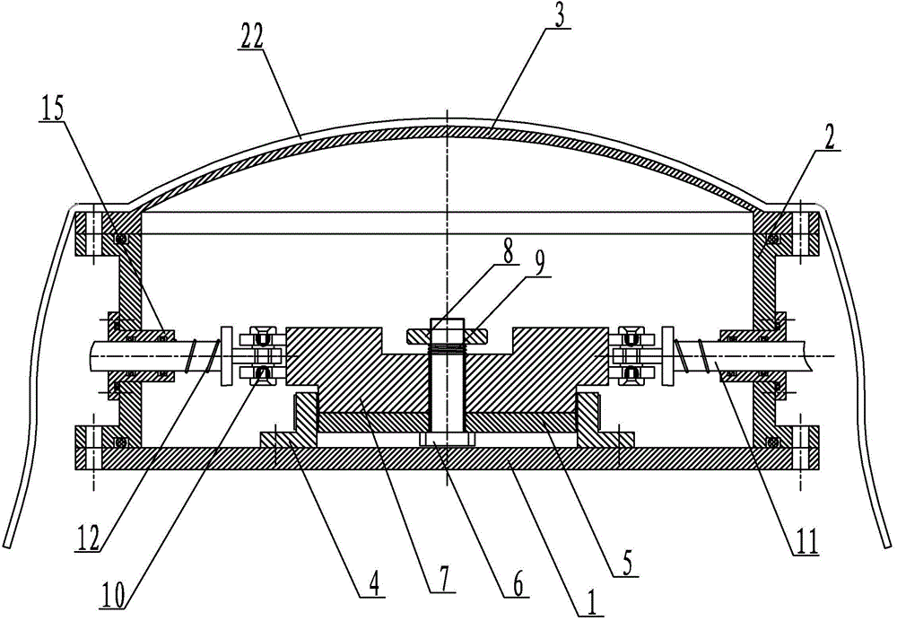
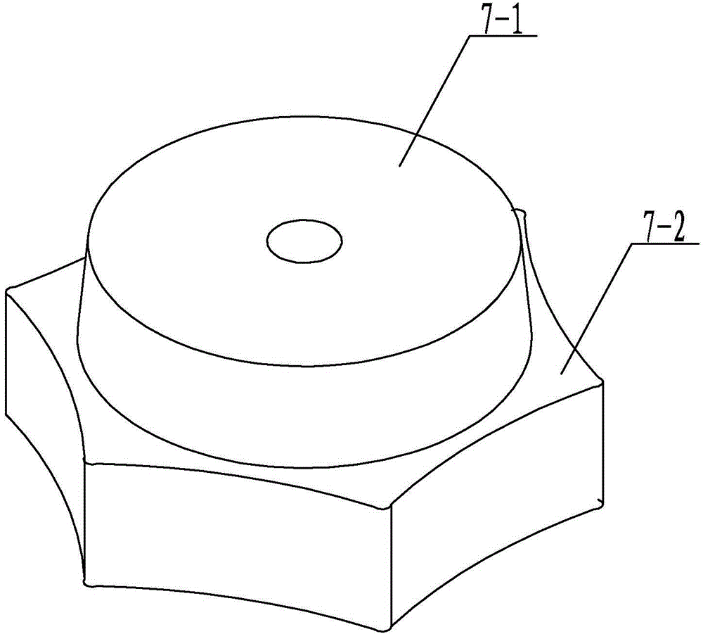
[0015] Specific implementation mode one: combine Figure 1-Figure 5 Describe this embodiment, a robotic jellyfish driven by a built-in cylindrical motor in this embodiment includes a chassis base 1, a sleeve 2, a mechanical abdominal cavity end cover 3, a cylindrical traveling wave ultrasonic motor 4, and a rotor compression end cover 5. Preload bolt 6, transmission cam 7, preload nut 8, preload spring 9, multiple thrust rod guide flanges 15, multiple double roller parts 10, multiple arm thrust rods 11, multiple auxiliary springs 12 and multiple articulated arms,

[0016] The mechanical abdominal cavity end cover 3, the sleeve 2 and the chassis base 1 are sealed and connected sequentially from top to bottom, the cylindrical traveling wave ultrasonic motor 4 is positioned and installed on the chassis base 1 through the bolt group, and the transmission cam 7 is connected through the pre-tightening bolt 6 , the pre-tightening nut 8, the pre-tightening spring 9 and the rotor comp...

specific Embodiment approach 2

[0022] Specific implementation mode two: combination Figure 4 and Figure 5 To illustrate this embodiment, each multi-joint arm of this embodiment includes a first connecting member 16, a second connecting member 17, a first connecting rod 18, a second connecting rod 19, a third connecting rod 20 and a fourth connecting rod 21. One end of the first connecting rod 18, one end of the second connecting rod 19, one end of the third connecting rod 20 and one end of the fourth connecting rod 21 are all connected to an arm thrust rod 11, and the other end of the first connecting rod 18 Connect with the middle part of the fourth connecting rod 21, the other end of the second connecting rod 19 is connected with the second connecting member 17, the other end of the third connecting rod 20 is connected with the first connecting member 16, the other end of the fourth connecting rod 21 Connect with the first connector 16. With such a setting, the movement is more flexible. Other compos...

specific Embodiment approach 3

[0023] Specific implementation mode three: combination figure 1 This embodiment will be described. In this embodiment, the rotor pressing end cover 5 and the pretension spring 9 are in interference fit. Such setting is convenient to ensure that the transmission cam 7 rotates smoothly under the drive of the cylindrical traveling wave ultrasonic motor 4 . Other compositions and connections are the same as those in Embodiment 1 or Embodiment 2.


PUM


Abstract

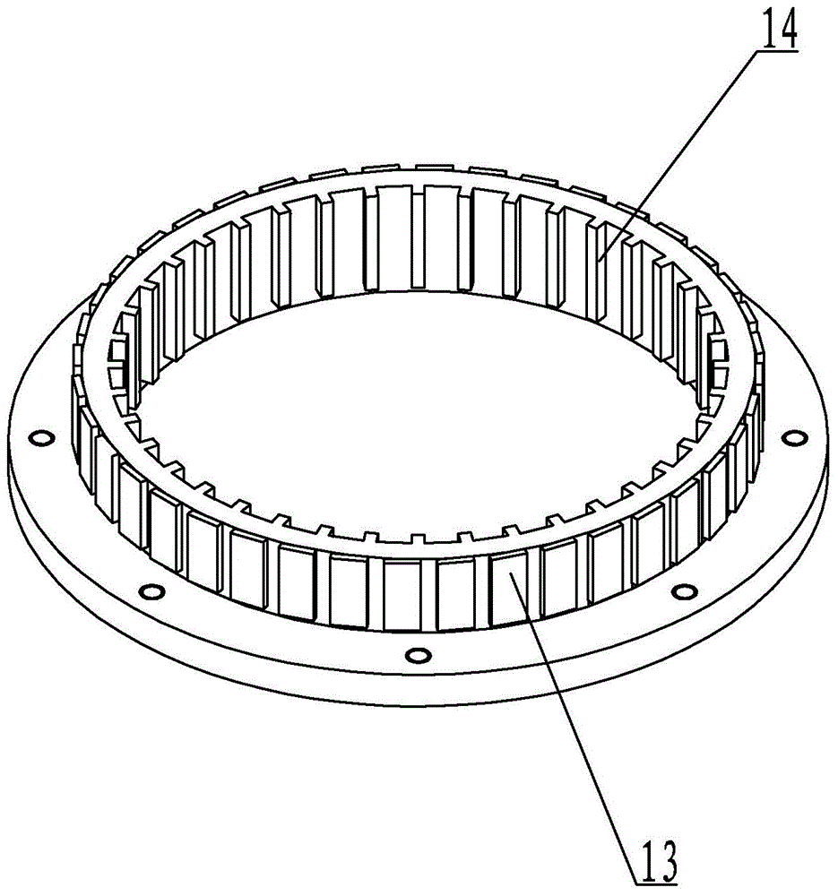
The invention relates to a machine jellyfish, in particular to a machine jellyfish driven by an embedded type cylindrical motor. The problem that an existing bionic jellyfish robot is limited in moving range, small in effective water spraying size and small in driving force and is not suitable for a complex water flow environment in nature is solved. A mechanical abdominal cavity end cover, a sleeve and a bottom disc base of the machine jellyfish are in sealing connection from top to bottom in sequence. A cylindrical traveling wave ultrasonic motor is arranged on the bottom disc base. A transmission cam is located in the middle of the cylindrical traveling wave ultrasonic motor. A plurality of piezoelectric ceramic pieces are evenly distributed on the outer cylinder wall of the cylindrical traveling wave ultrasonic motor. A plurality of rectangular bosses which are arrayed vertically are evenly distributed on the inner cylinder wall of the cylindrical traveling wave ultrasonic motor. The other end of each arm pushing force rod is connected with a multi-joint arm. Each arm pushing force rod and the sleeve are connected through a pushing force rod guiding flange. An auxiliary spring is arranged between each pushing force guiding flange and an arm pushing force rod close to one side of a double-idler-wheel part. The machine jellyfish is used for unmanned underwater carrying.

Description

technical field [0001] The invention relates to a robotic jellyfish, in particular to a robotic jellyfish driven by a built-in cylindrical motor. Background technique [0002] The bionic unmanned underwater carrier robot is a mechanical system developed and designed with reference to underwater bionic prototypes (such as fish, turtles, etc.). It has the characteristics of high efficiency and quietness. Therefore, it has important military and commercial value, attracting more and more researchers to work in this area. Generally speaking, the propulsion forms of underwater bionic prototypes can be roughly divided into three forms: body caudal fin propulsion (BCF), pectoral fin propulsion (MPF), and jet propulsion (JP). From the perspective of machine bionics, based on BCF and MPF The mechanical system of the propulsion prototype has the disadvantages of complex structure and difficult control. On the contrary, the system based on the jet propulsion prototype has the characte...

Claims


Application Information

Patent Timeline
Patent Type & Authority Applications(China)
IPC IPC(8): B63H1/30B63H11/02
Inventor 陈维山董帝渤韩臻博石胜君侯珍秀刘军考
Owner HARBIN INST OF TECH
Learn More