A laminated magnetic levitation propeller

A thruster and magnetic levitation technology, which is applied in the direction of propulsion system, magnetic attraction or thrust holding device, electrical components, etc., can solve the problem of thrust reduction, etc., and achieve reduced energy consumption, easy control, and the process of advancing and retracting reversible effect

Active Publication Date: 2017-12-12
CHANGZHOU INST OF TECH
View PDF1 Cites 0 Cited by
  • Summary
  • Abstract
  • Description
  • Claims
  • Application Information

AI Technical Summary

Problems solved by technology

In this application, the magnitude of the thrust is inversely proportional to the square of the distance. When the stroke distance is long, the thrust will be significantly reduced, and it can only be applied to occasions where the propulsion distance is relatively short.

Method used


Image

  • A laminated magnetic levitation propeller
  • A laminated magnetic levitation propeller
  • A laminated magnetic levitation propeller

Examples


Embodiment

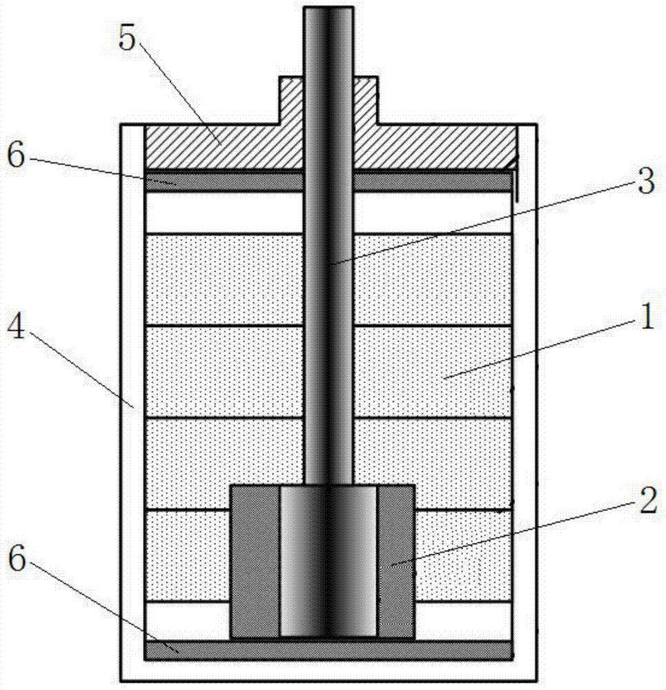
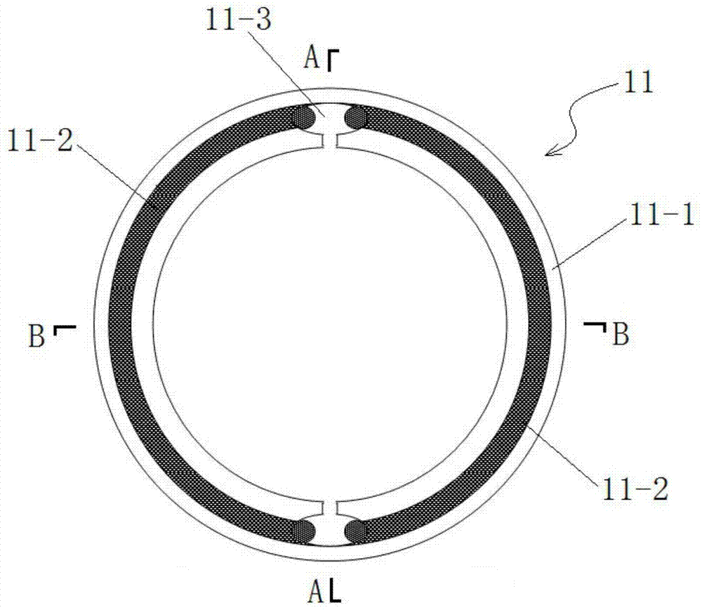
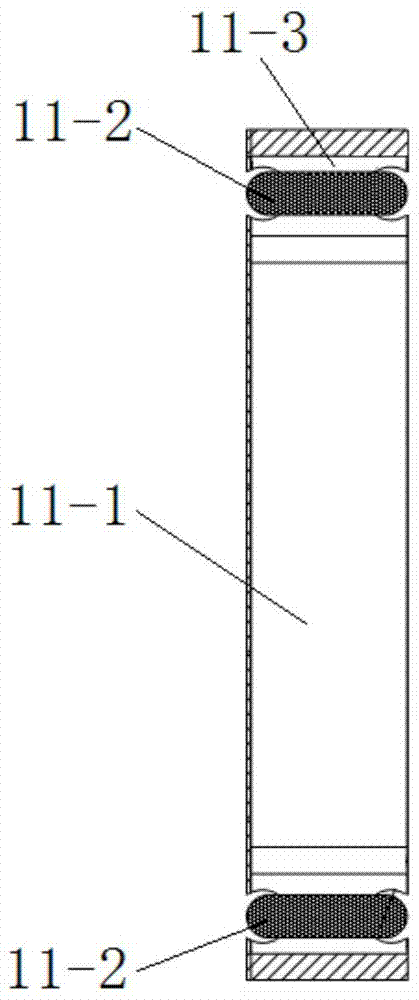
[0044] Such as Figure 1 to Figure 15 As shown, a laminated magnetic levitation thruster of this embodiment includes a casing, a static magnetic pole 1, a moving magnetic pole 2, a propulsion rod 3 and a drive circuit, and the static magnetic pole 1 is stacked together by several static magnetic pole units 11 at the same angle The static magnetic pole unit 11 includes a magnetic circuit ring 11-1 and a coil 11-2. An annular groove is respectively provided on the two ends of the magnetic circuit ring 11-1, and the annular groove is opened in the magnetic circuit ring 11-1. The two coil installation holes 11-3 on the top are divided into two semicircular coil installation grooves 11-4, which form two opposite magnetic claws, and each of the two coil installation grooves 11-4 is provided with a coil 11-4. 2, and the ends of the same names of the two coils 11-2 are connected, after the two coils 11-2 of the static magnetic pole unit 11 are energized, the direction of the magnetic ...


PUM


Abstract

The invention discloses a laminated magnetic levitation thruster, which belongs to the field of electromagnetic technology. The invention includes a casing, a static magnetic pole, a moving magnetic pole, a push rod and a drive circuit. The static magnetic pole is composed of several static magnetic pole units stacked together at the same angle. The static magnetic pole unit includes a magnetic circuit ring and a coil. The magnetic circuit ring is symmetrically arranged Two semicircular coils, and the ends of the two coils with the same name are connected; the moving magnetic pole includes a permanent magnetic ring and a soft iron core, and the soft iron core is set inside the permanent magnetic ring, and the magnetic flux direction of the moving magnetic pole is the diameter direction of the moving magnetic pole; the propulsion rod is fixed on the moving magnetic pole; each static magnetic pole unit has a drive circuit that independently controls the current direction and current on-off of the coil in the static magnetic pole unit. The present invention utilizes laminated magnetic poles to realize continuous propulsion, which can be advanced at high speed and long distance. The thrust is kept constant during the propulsion process, and the power consumption is low. The effect of electromagnetic force is fully utilized, and the laminated magnetic poles can also be used to realize segmental propulsion, which is suitable for different propulsion distances.

Description

technical field [0001] The invention relates to a magnetic thruster, more specifically, to a laminated magnetic levitation thruster. Background technique [0002] Common propellers include pneumatic propellers and electric propellers, and electric propellers are divided into motor drive and electromagnetic drive according to the driving mode. The motor-driven thruster generally needs to be decelerated by a gear reducer to push the propulsion rod to move, so that the rotational motion of the motor can be changed into a linear motion, and the forward and reverse rotation of the motor is used to complete the push rod action. It is suitable for long-distance and slow-moving occasion. Electromagnetically driven thrusters generally use the attraction and repulsion of magnetic poles to realize the movement of the propulsion rod. Since the thrust of existing electromagnetically driven thrusters is inversely proportional to the square of the distance, the thrust will be significantl...

Claims


Application Information

Patent Timeline
Patent Type & Authority Patents(China)
IPC IPC(8): H02K41/02H02K33/00H02N15/00
Inventor 高敏马会全王雁平
Owner CHANGZHOU INST OF TECH
Why Eureka
Try Eureka