Automatic ash discharge system

A fully automatic, fire exhaust technology, applied in the field of combustion furnaces, which can solve problems such as hazards and poor continuous fuel supply capability.

Active Publication Date: 2021-05-11
ANHUI JINSHANG MACHINERY MFG CO LTD
View PDF10 Cites 0 Cited by
  • Summary
  • Abstract
  • Description
  • Claims
  • Application Information

AI Technical Summary

Problems solved by technology

[0002] The combustion furnace is a common combustion equipment. When the existing combustion furnace is burning fuel, the continuous supply capacity of the fuel is poor, and the flame flue gas generated at the same time contains a large amount of dust, which enters along the flame flue gas. In the connected heating equipment, it will cause harm to it, for which a fully automatic ash discharge system is required

Method used


Image

  • Automatic ash discharge system
  • Automatic ash discharge system
  • Automatic ash discharge system

Examples


Embodiment 1

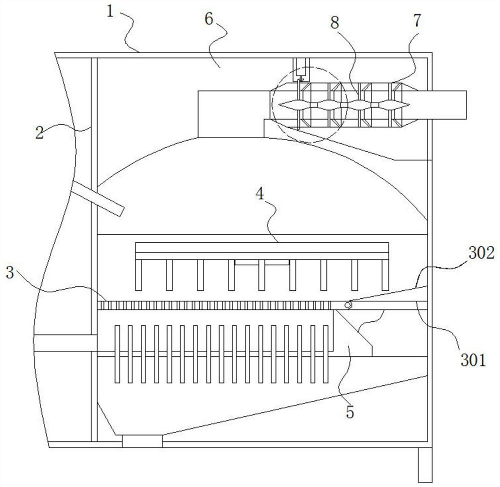
[0033] One end of the air intake box 5 near the dividing plate 2 is equipped with an intake pipe fixedly socketed with the dividing plate 2, the top of the air intake box 5 is provided with a vent hole running through the combustion plate 3, and the bottom of the air intake box 5 is fixedly sleeved with a The heat conducting rods arranged equidistantly in the length direction, and the heat conducting rods stretch out from the bottom of the air intake box 5, the bottom of the movable plate 301 is equipped with a guide plate positioned at the bottom of the combustion furnace 1 and inclined, and the guide plate extends to the air intake box 5 Below the bottom of the combustion plate 3, a feed pipe inclined downwards is installed above the side of the combustion plate 3 close to the partition plate 2;

Embodiment 2

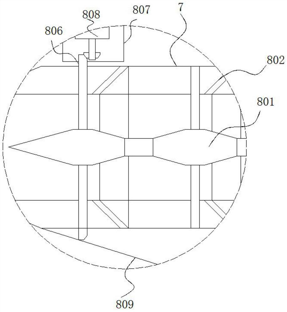
[0035] The driving mechanism 808 includes a gear with the inner core of the gear ring. The inner ring of the gear is fixedly sleeved with a rotating shaft. One end of the rotating shaft is installed with a third motor fixedly connected to the inner wall of the installation groove 807 through a coupling. The adsorption collar 802 is far away from the fire exhaust. The surface of the discharge end of channel 7 is provided with adsorption grooves of annular structure distributed along its diameter direction, and the cleaning device is attached to the adsorption grooves. The cross section of the adsorption grooves is an isosceles triangle structure.

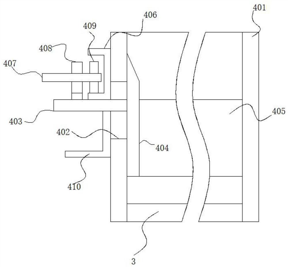
[0036] Working principle: when in use, the fuel in the feed pipe enters the top of the combustion plate 3 downwards, and then the first motor connected to the rotating shaft 407 on the push assembly 4 is started, and the rotation 407 drives the push gear 409 and the extrusion wheel 408 at this time Rotate at the same time, when the sque...


PUM


Abstract

The present invention belongs to the technical field of combustion furnaces, especially a fully automatic ash discharge system. The following proposal is now proposed, including a combustion furnace. A vertical partition is arranged inside the combustion furnace. One side of the partition is fixed with a horizontal The top of the combustion plate is provided with a push mechanism for fuel push, the bottom of the combustion plate is fixed with an air intake box, the top of the push mechanism is installed with a circular arc-shaped inner wall fixed to the inner wall of the top of the combustion furnace The heat insulation board of the groove, the top of the groove in the heat insulation board is provided with a fire discharge channel, and the interior of the fire discharge channel is installed with an auxiliary component for cleaning. The invention realizes the continuous propulsion and discharge of fuel, realizes continuous feeding of fuel, utilizes the preheating in fuel waste, improves energy utilization efficiency, removes residual dust in flame smoke, and improves the cleanliness of flame smoke , Reduce the harm of flame smoke to other equipment.

Description

technical field [0001] The invention relates to the technical field of combustion furnaces, in particular to a fully automatic ash discharge system. Background technique [0002] The combustion furnace is a common combustion equipment. When the existing combustion furnace is burning fuel, the continuous supply capacity of the fuel is poor, and the flame flue gas generated at the same time contains a large amount of dust, which enters along the flame flue gas. In the connected heating equipment, it will cause harm to it, for which a fully automatic ash discharge system is required. Contents of the invention [0003] The fully automatic ash discharge system proposed by the invention solves the problems existing in the prior art. [0004] In order to achieve the above object, the present invention adopts the following technical solutions: [0005] The fully automatic ash removal system includes a combustion furnace, the interior of the combustion furnace is provided with a ...

Claims


Application Information

Patent Timeline
Patent Type & Authority Patents(China)
IPC IPC(8): F23J1/06
CPCF23J1/06
Inventor 杨锴
Owner ANHUI JINSHANG MACHINERY MFG CO LTD
Why Eureka
Try Eureka