Wave-driven ship

A wave and wave energy technology, applied in ship construction, ship propulsion, ship components, etc., can solve the problems of discontinuous energy conversion, large installation size, and large energy loss, and achieve the effect of improving transmission efficiency and reducing installation size.

Inactive Publication Date: 2019-01-11
HARBIN ENG UNIV
View PDF13 Cites 0 Cited by
  • Summary
  • Abstract
  • Description
  • Claims
  • Application Information

AI Technical Summary

Problems solved by technology

This kind of mechanism has large installation size (the movement space of the floating body is independent of the installation space of the energy harvesting and conversion mechanism), discontinuous energy conversion (using ratchet pawl one-way limit device, only half of the energy can be collected), and more energy loss. (When multiple sets of energy conversion devices are used, the use of intermediate devices such as hydraulic systems to store energy will cause energy loss, and the collected wave energy cannot be converted into propeller kinetic energy to a large extent, and a large amount of energy will be retained in the hydraulic energy storage system) and other shortcomings. Design a A compact and high-efficiency conversion device on board the ship, it is a new attempt to use it in the power of the hull

Method used


Image

  • Wave-driven ship
  • Wave-driven ship
  • Wave-driven ship

Examples


Embodiment 1

[0016] The object of the present invention is to provide a transmission mechanism that drives the ship to sail by sea waves, so as to realize the ship's sailing under emergency sea conditions. In order to achieve the above object, the present invention includes four aspects: a hull, a wave energy capture device installed with the hull, a mechanical energy conversion device, and a mechanical energy output device. The hull provides the installation space for the entire device, serving as the carrier and the final power output object of the entire system. The wave energy capture device collects the vertical wave potential energy and converts it into mechanical energy in the form of bidirectional rotation. The mechanical energy conversion device converts the bidirectional rotational mechanical energy of the capture device into unidirectional continuous rotational mechanical energy and transmits it to the output device for the ship to drive. The innovations of the present invention...

Embodiment 2

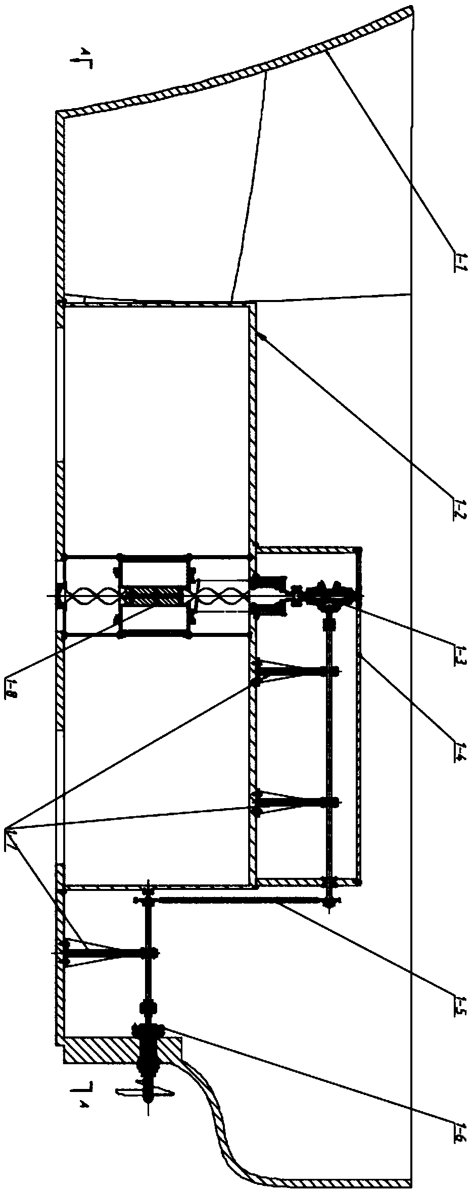
[0018] figure 1 : Overall scheme of wave-driven ship and transmission device. The overall plan includes: hull 1-1, water tank 1-2, mechanical energy conversion device 1-3 (see Figure 4 ), upper installation storehouse 1-4, chain drive 1-5, mechanical energy output device 1-6, shaft bearing mounting bracket 1-7, wave energy capture device 1-8. The A-A sectional view is taken from the bottom of the ship.

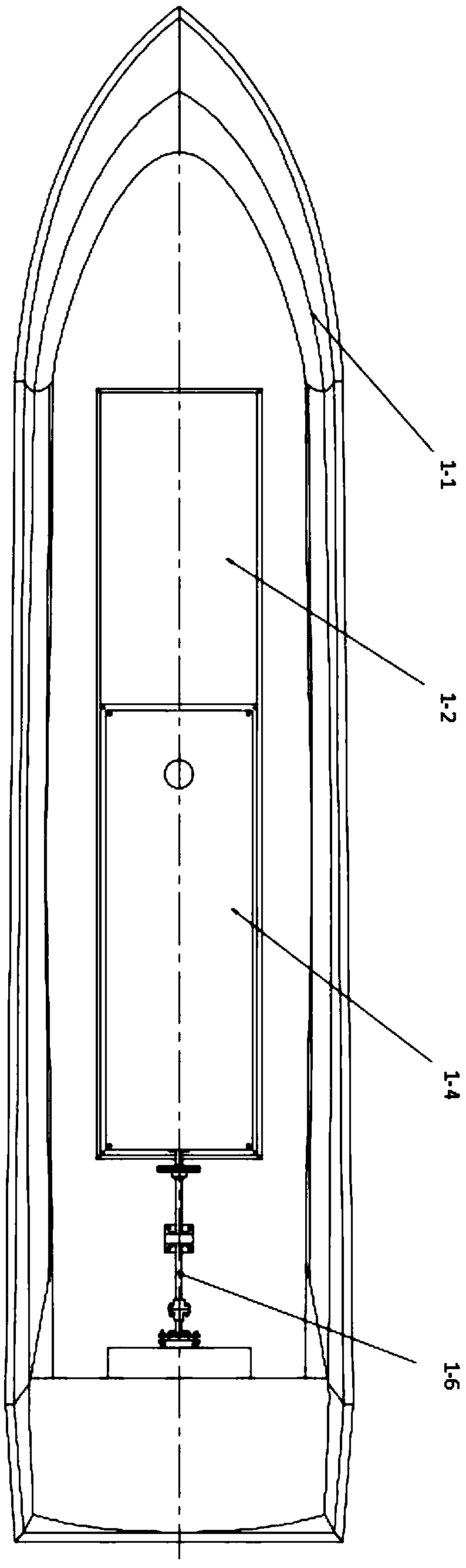
[0019] figure 2 Top view of wave-driven boat and transmission. The top view includes: a hull 1-1, a water tank 1-2, an upper installation tank 1-4, and a mechanical energy output device 1-6. It can be seen from the top view that the whole device is symmetrically installed on the left and right sides of the hull.

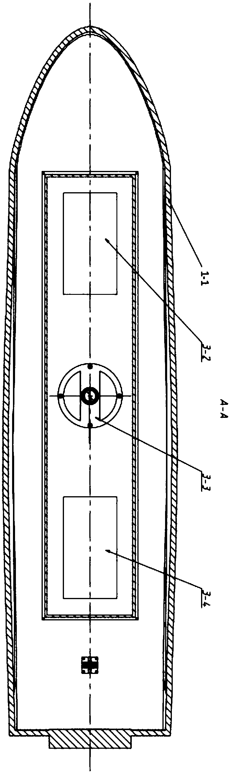
[0020] image 3 A-A sectional view of wave-driven ship and transmission device. A-A sectional view includes: a hull 1-1, a first water inlet 3-2 at the bottom of the ship, an underframe 3-3 for installing a capture device, and a second water inlet 3-4 at the...

Embodiment 3

[0025] Combine below figure 1 , 2 , 3, 4, and 5 illustrate specific embodiments of the present invention. The following definition of the direction of rotation is as follows: clockwise rotation viewed from the bottom of the hull is forward rotation, and clockwise rotation viewed from the stern to the bow is forward rotation.

[0026] Since floats of different shapes can capture unused wave energy under the same effective displacement volume, the vertical cylindrical float with higher energy capture efficiency is selected as the float type selection. Long cuboid helical drive nut 4-14 installation space.

[0027]The screw rods 4-8 are single-helix shaftless screw rods, the cross section of which is a chamfered rectangle, and its structure is formed by rotating and scanning the chamfered rectangle along the axial direction. The inner drive surface of the screw drive nut 4-14 is engaged with the outer surface of the screw rod 4-8, and a lubricating gap of 0.1 mm is reserved in...


PUM


Abstract

The invention discloses a wave-driven ship, belonging to the field of wave energy utilization. The vertical displacement of a floater with respect to the ship hull is taken as input power when the wave is captured by a hollow vertical cylindrical floater installed inside the ship hull in the undulating state. The vertical displacement variation of the floater is converted into bi-directional rotational power by a screw transmission mechanism mounted on the floater. The bidirectional rotational power of the helical rod is converted into unidirectional rotational mechanical energy by the unidirectional conversion device of a bevel gear set. In order to reduce the power loss of the intermediate conversion link, the power of the one-way conversion device is directly output to the propeller stern shaft for hull drive. Different from the wave energy conversion device installed outside the ship hull or fixed on the sea bed, the conversion device in this design has the advantages of convenientmovement of installation on ships, simple and compact structure, stable output, high conversion efficiency and so on.

Description

technical field [0001] The invention relates to the field of wave energy utilization, in particular to a wave-driven ship. Background technique [0002] Wave drive device is a research hotspot in the field of wave energy utilization in recent years. Its commonly used mechanism is mainly based on the buoyant body capturing the wave energy and then converting the wave energy through piston-crank slider, rack and pinion and other mechanisms. This kind of mechanism has large installation size (the movement space of the floating body is independent of the installation space of the energy harvesting and conversion mechanism), discontinuous energy conversion (using ratchet pawl one-way limit device, only half of the energy can be collected), and more energy loss. (When multiple sets of energy conversion devices are used, the use of intermediate devices such as hydraulic systems to store energy will cause energy loss, and the collected wave energy cannot be converted into propeller...

Claims


Application Information

Patent Timeline
Patent Type & Authority Applications(China)
IPC IPC(8): B63H19/04F03B13/14
CPCB63H19/04F03B13/14Y02E10/30Y02T70/5236
Inventor 刘少刚刘兵锋赵丹高春晓李征远
Owner HARBIN ENG UNIV
Why Eureka
Try Eureka