Single Diaphragm Hydraulic Control Valve

A technology for hydraulic control valves and diaphragms, applied in the direction of diaphragm valves, diaphragms, valve devices, etc., can solve the problems of insufficient sealing, easy jamming of impurities at the connection between the diaphragm and the valve seat, etc., to achieve convenient control and easy solution in the valve Clogging, life-enhancing effect

Active Publication Date: 2018-09-21
SICHUAN HAIYING VALVE CO LTD
View PDF8 Cites 0 Cited by
  • Summary
  • Abstract
  • Description
  • Claims
  • Application Information

AI Technical Summary

Problems solved by technology

When the hydraulic control valve with this structure is in use, the connection between the diaphragm and the valve seat is likely to be blocked by impurities, which is likely to cause problems such as insufficient sealing, and requires frequent maintenance or replacement during use.

Method used


Image

  • Single Diaphragm Hydraulic Control Valve
  • Single Diaphragm Hydraulic Control Valve
  • Single Diaphragm Hydraulic Control Valve

Examples


Embodiment 1

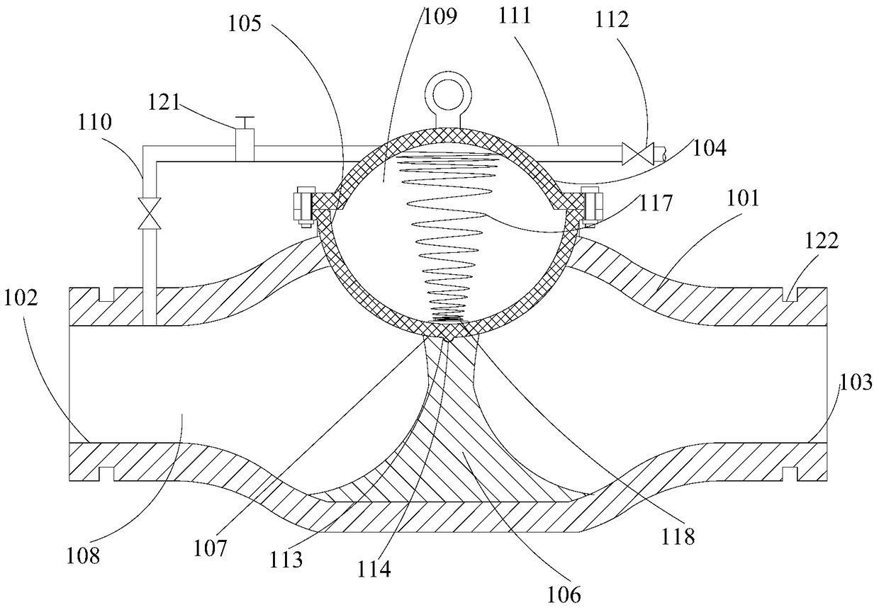
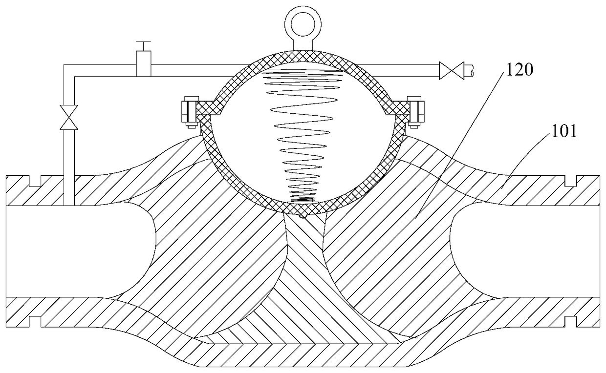
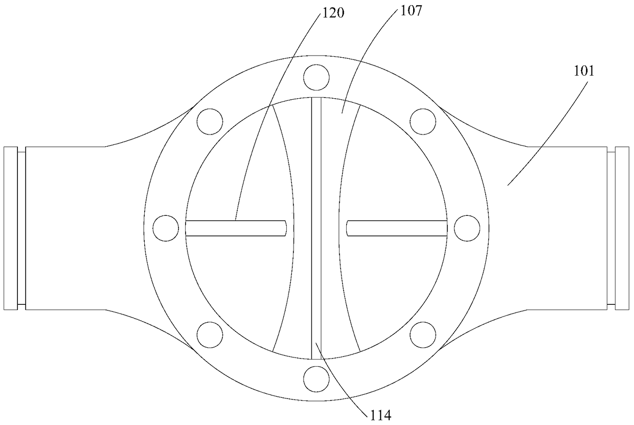
[0080] A single-diaphragm hydraulic control valve, comprising a main valve 101, the left and right ends of the main valve 101 are respectively an inlet port 102 and an outlet port 103, and the side of the main valve 101 is provided with a valve cover 104 detachably connected thereto. A hemispherical diaphragm 105 is arranged between the valve cover 104 and the main valve 101. The inner spherical surface of the diaphragm 105 faces the valve cover 104. The diaphragm 105 is made of elastic material and can be elastically deformed; the main valve 101 has a blocking structure inside 106, the blocking structure 106 includes an arc-shaped blocking surface 107 fitted with the outer spherical surface of the diaphragm 105, and the blocking effect of the blocking structure 106 and the diaphragm 105 can block the connection between the inlet port 102 and the outlet port 103; the inlet port 102. A water inlet chamber 108 is formed between the diaphragm 105 and the blocking structure 106, an...

Embodiment 2

[0082] A single-diaphragm hydraulic control valve, comprising a main valve 101, the left and right ends of the main valve 101 are respectively an inlet port 102 and an outlet port 103, and the side of the main valve 101 is provided with a valve cover 104 detachably connected thereto. A hemispherical diaphragm 105 is arranged between the valve cover 104 and the main valve 101. The inner spherical surface of the diaphragm 105 faces the valve cover 104. The diaphragm 105 is made of elastic material and can be elastically deformed; the main valve 101 has a blocking structure inside 106, the blocking structure 106 includes an arc-shaped blocking surface 107 fitted with the outer spherical surface of the diaphragm 105, and the blocking effect of the blocking structure 106 and the diaphragm 105 can block the connection between the inlet port 102 and the outlet port 103; the inlet port 102. A water inlet chamber 108 is formed between the diaphragm 105 and the blocking structure 106, an...


PUM


Abstract

The invention provides a single-diaphragm hydraulic control valve, and belongs to the field of valves. The single-diaphragm hydraulic control valve comprises a main valve, wherein the left and right ends of the main valve are respectively an inlet end and an outlet end; a valve cover detachably connected with the main valve is arranged at the side part of the main valve; a semispherical diaphragm is arranged between the valve cover and the main valve; the inner spherical surface of the diaphragm is towards the valve cover; the diaphragm is manufactured by an elastic material, and can generate elastic deformation; the main valve has a stop structure inside; the stop structure comprises an arched stop surface bonded with the outer spherical surface of the diaphragm; the connection between the inlet end and the outlet end can be stopped through a stop effect of the stop structure and the diaphragm; a water inlet cavity and a control cavity are communicated through a guide pipe; the guide pipe is connected with an adjusting pipe; and a pilot valve is arranged on the adjusting pipe. The hydraulic control valve and a traditional hydraulic control valve have qualitative differences in the working process, so that the service life of the whole hydraulic control valve is prolonged, and the engineering cost is reduced.

Description

technical field [0001] The invention relates to the field of valves, in particular to a single-diaphragm hydraulic control valve. Background technique [0002] Valves are one of the most commonly used components in various mechanical and engineering fields. Valves are divided into various types according to their functions and structures. [0003] The hydraulic control valve is a valve controlled by water pressure. The hydraulic control valve is composed of a main valve and its attached conduit, pilot valve, needle valve, ball valve and pressure gauge. According to different purposes, functions and places, it can be evolved into remote control float valve, pressure reducing valve, slow-closing noise reduction check valve, flow control valve, pressure relief valve, hydraulic electric control valve, water pump control valve, electric control valve, limiter flow control valves, emergency shut-off valves, etc. Filters, etc. should be installed in front of the hydraulic contro...

Claims


Application Information

Patent Timeline
Patent Type & Authority Patents(China)
IPC IPC(8): F16K7/17F16K31/385
CPCF16K7/17F16K31/385
Inventor 刘欢刘全胜
Owner SICHUAN HAIYING VALVE CO LTD
Why Eureka
Try Eureka