End face sealing structure used for rotary compensator and rotary compensator

A rotary compensator and end-face sealing technology, which is applied to expansion compensation devices for pipelines, adjustable connections, pipes/pipe joints/pipes, etc., can solve the problems of poor sealing effect and easy wear of the rotary compensator. Good sealing effect and the effect of reducing torque difference

Active Publication Date: 2016-01-20
JIANGSU BT PIPE CO LTD
View PDF7 Cites 1 Cited by
  • Summary
  • Abstract
  • Description
  • Claims
  • Application Information

AI Technical Summary

Problems solved by technology

[0005] In view of the problems that the existing rotary compensator is easy to wear and the sealing effect is not good, the present invention proposes an end face sealing structure and a rotary compensator with better sealing performance

Method used


Image

  • End face sealing structure used for rotary compensator and rotary compensator
  • End face sealing structure used for rotary compensator and rotary compensator
  • End face sealing structure used for rotary compensator and rotary compensator

Examples


Embodiment 1

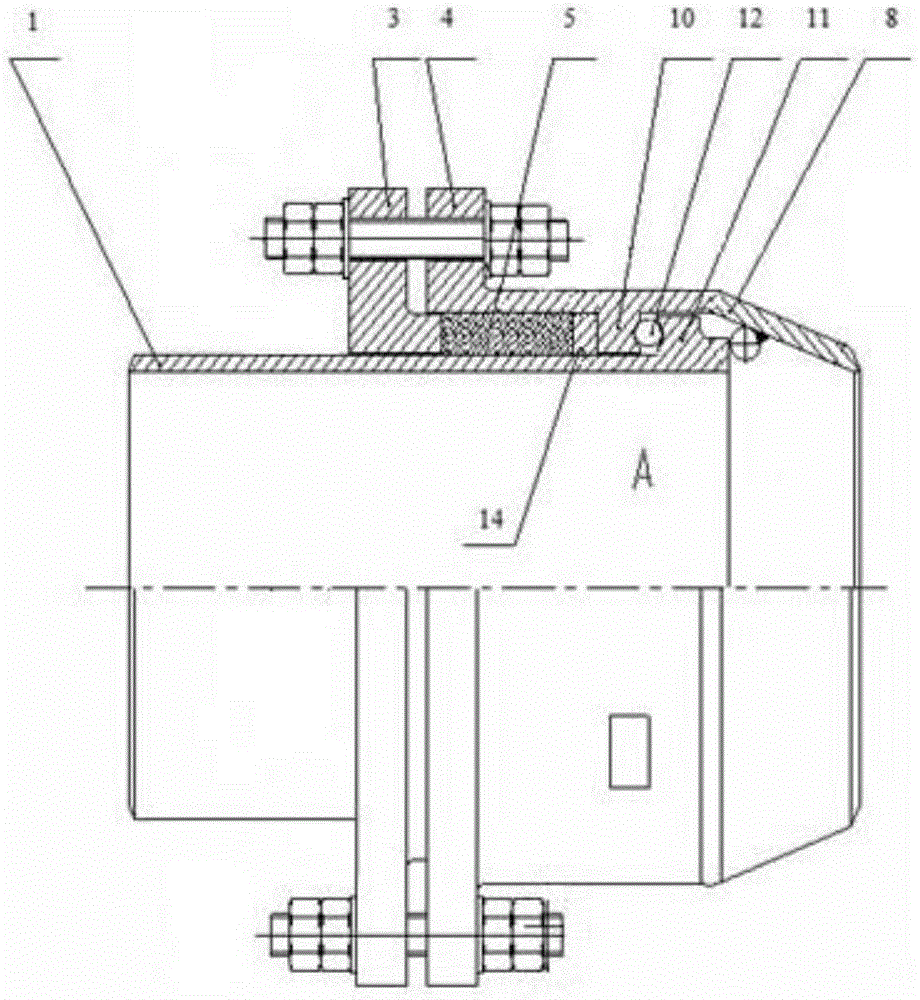
[0025] like figure 1 As shown, the rotary compensator described in this embodiment includes an inner tube 1, an outer tube 4, a connecting tube 8, a packing flange 3 and an O-shaped end face sealing sliding ring 12, and the outer tube 4 and the connecting tube 8 are integrally formed structure. The outer sleeve 4 is set on the inner tube 1, and one end of the inner tube 1 is inserted into the connecting pipe 8 through the outer sleeve 4, and the packing flange 3 is set on the inner tube 1, and one end thereof extends into the outer sleeve 4. An annular inner boss 10 is provided on the inner surface of the outer casing 4, and an annular outer boss 11 is arranged on the outer surface of the inner tube 1, between the annular inner boss 10 and the end of the packing flange 3 extending into the outer casing 4 A sealing packing 5 is provided, and an anti-impact plate 14 is provided between the sealing packing 5 and the annular inner boss 10, and a corresponding annular V-shaped gro...

Embodiment 2

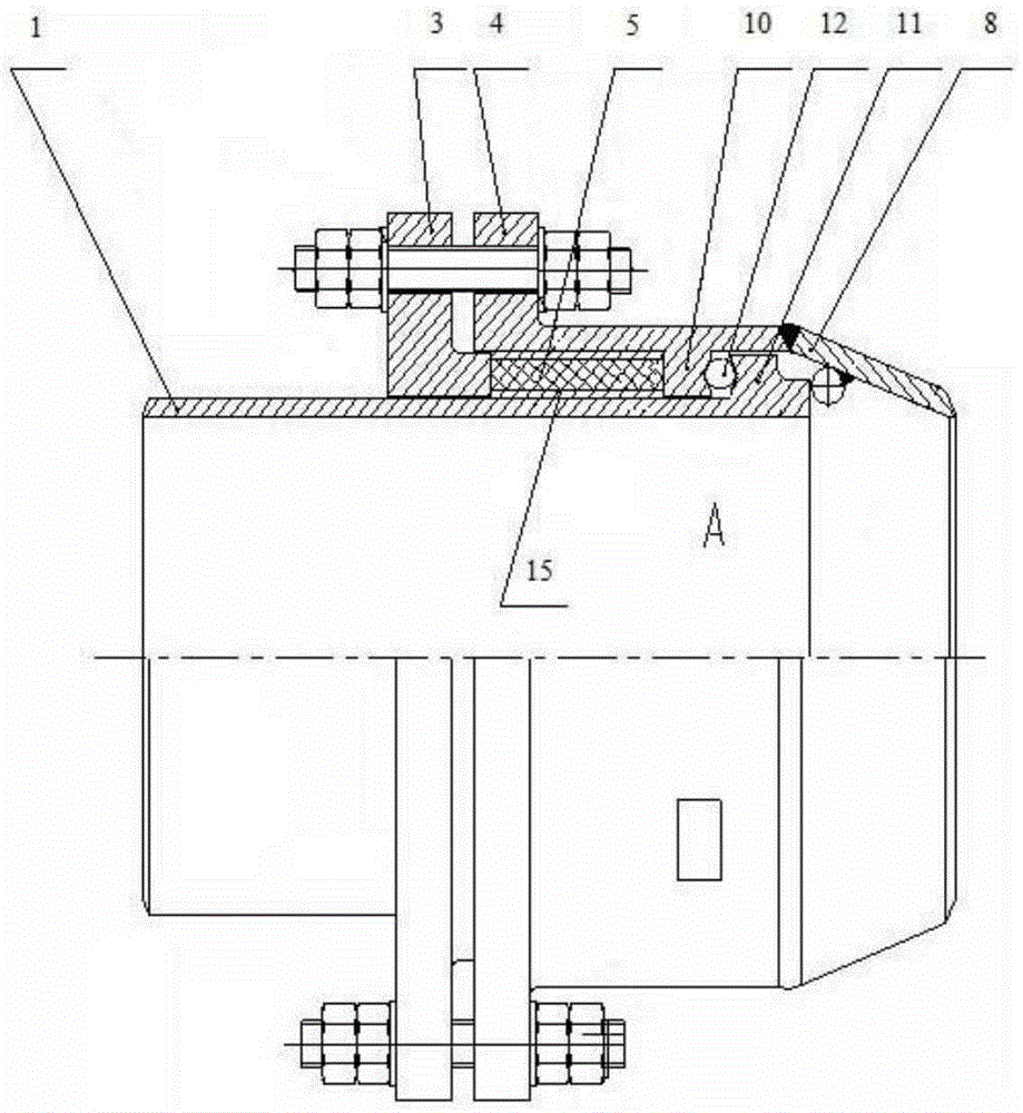
[0027] like figure 2 As shown, the rotary compensator described in this embodiment includes an inner tube 1, an outer tube 4, a connecting tube 8, a packing flange 3 and an O-shaped end face sealing sliding ring 12, the outer tube 4 is set on the inner tube 1, and the inner tube One end of 1 is inserted into the connecting pipe 8 through the outer casing 4, and the packing flange 3 is set on the inner pipe 1, and one end thereof extends into the outer casing 4. An annular inner boss 10 is provided on the inner surface of the outer casing 4, and an annular outer boss 11 is arranged on the outer surface of the inner tube 1, between the annular inner boss 10 and the end of the packing flange 3 extending into the outer casing 4 A sealing packing 5 is provided, and a wear-resistant carbon fiber layer 15 is provided between the sealing packing 5 and the outer surface of the inner tube 1 , and between the sealing packing 5 and the inner surface of the outer casing 4 . There is a co...

Embodiment 3

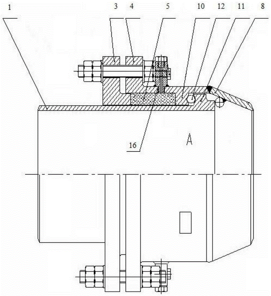
[0029] like image 3 As shown, the rotary compensator described in this embodiment includes an inner tube 1, an outer tube 4, a connecting tube 8, a packing flange 3 and an O-shaped end face sealing sliding ring 12, the outer tube 4 is set on the inner tube 1, and the inner tube One end of 1 passes through the outer casing 4 and is inserted into the connecting pipe 8. The packing flange 3 is set on the inner pipe 1, and one end thereof extends into the outer casing 4. The inner surface of the outer casing 4 is provided with an annular inner boss 10. The outer surface of the pipe 1 is provided with an annular outer boss 11, and a sealing packing 5 is provided between the annular inner boss 10 and the end of the packing flange 3 extending into the outer casing 4, and the annular inner boss 10 and the annular outer boss There is a corresponding annular V-shaped groove on the opposite surface of 11, and the O-shaped end face sealing sliding ring 12 is assembled in the two annular ...


PUM


Abstract

The invention discloses an end face sealing structure used for a rotary compensator and the rotary compensator with the sealing structure. The end face sealing structure comprises an annular inner boss arranged on the inner surface of an outer sleeve, an annular outer boss arranged on the outer surface of an inner pipe, and an end face sealing ring arranged between the annular outer boss and the annular inner boss. The end face sealing structure is characterized in that the contact face of the annular inner boss and the end face sealing ring and the contact face of the annular outer boss and the end face sealing ring are each provided with an annular V-shaped groove; and the two sides, making contact with the annular inner boss and the annular outer boss, of the end face sealing ring are each in the shape of an arc and stretch into the corresponding V-shaped grooves respectively. The end face sealing structure can effectively solve the problem that an existing rotary compensator is prone to abrasion, and the sealing effect is obviously improved.

Description

technical field [0001] The invention relates to an end face sealing structure for a rotary compensator and the rotary compensator. Background technique [0002] Compensation devices are generally required to be installed and used in pipelines in industries such as electric power, petroleum, chemical industry, and heat power. Existing compensation devices usually include rotary compensators, bellows compensators, sleeve compensators, spherical compensators, etc., used to compensate pipeline shafts direction and radial displacement. When the pipeline transports high-temperature and high-pressure media, the requirements for the rotary compensator are higher: not only must there be sufficient displacement compensation, but also good sealing performance and long service life. [0003] Existing rotary compensators solve the problem of pipeline leakage of high-temperature and high-pressure media by installing end face seals in the sealing cavity, such as Chinese patent 20061004130...

Claims


Application Information

Patent Timeline
Patent Type & Authority Applications(China)
IPC IPC(8): F16L27/08F16L51/00
CPCF16L27/0832F16L51/00
Inventor 洪磊洪亮尹明华
Owner JIANGSU BT PIPE CO LTD
Why Eureka
Try Eureka