Control device for drive motors

a technology of control device and drive motor, which is applied in the direction of electric devices, vehicle sub-unit features, propulsion by batteries/cells, etc., can solve the problems of loss of torque balance between loss of the driving force of the right and the left wheels, etc., and achieve the effect of simplifying the structure of the clutch mechanism

Active Publication Date: 2013-09-10
TOYOTA JIDOSHA KK
View PDF6 Cites 1 Cited by
  • Summary
  • Abstract
  • Description
  • Claims
  • Application Information

AI Technical Summary

Benefits of technology

[0011]Thus, according to the present invention, the control system is provided with at least two driving motors individually connected with a wheel of a vehicle to drive the wheel, and those driving motors are controlled by the current control means connected individually therewith. Therefore, each of the wheels can be driven independently. In addition, the control system is provided with the switching means that allows one of the current control means to supply the current to both of the driving motors. Therefore, for example, in case a performance of the other current control means is degraded, the current can be supplied to both of the driving motors without using the other current control means. Further, in case of driving the vehicle by thus supplying the current to both of the driving motors from one of the current control means, the clutch interposed between one of the driving motor and the wheel connected therewith interrupts torque transmission to the wheel. Therefore, a torque difference between the wheels can be reduced. For this reason, the vehicle is allowed to drive stably even in case of supplying the current to both of the driving motors from one of the current control means.
[0012]Specifically, the clutch interrupts the torque transmission in case of synchronizing the rotor phase of the driving motors under the situation in which the current is being supplied to both of the driving motors from one of the current control means. Therefore, the torque for adjusting the rotor phase will not be transmitted to the wheel. For this reason, the rotor phase of the driving motors can be synchronized without deteriorating the running stability of the vehicle.
[0014]As described, according to the present invention, the clutch includes a one-way clutch that transmits the torque only in one direction. Therefore, even in case the driving motor outputs a negative torque, the negative torque will not be transmitted to the wheel so that the above-explained advantages can be achieved. In addition to the above-explained advantages, a structure of the clutch mechanism can be simplified.

Problems solved by technology

Therefore, if one of those driving motors is in trouble, or if one of electric current sources is in trouble, the driving force of the right and the left wheels lose their balance.
Therefore, if those motors thus rotated out of phase are driven together by the common current outputted from the one of the inverters when the other inverter is in trouble, a torque balance between the right and the left wheel may be lost.

Method used


Image

  • Control device for drive motors
  • Control device for drive motors
  • Control device for drive motors

Examples


Embodiment Construction

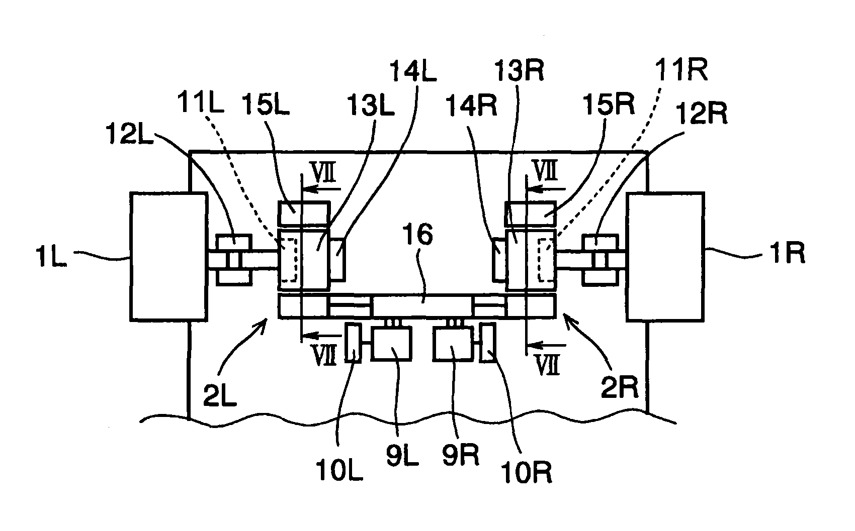
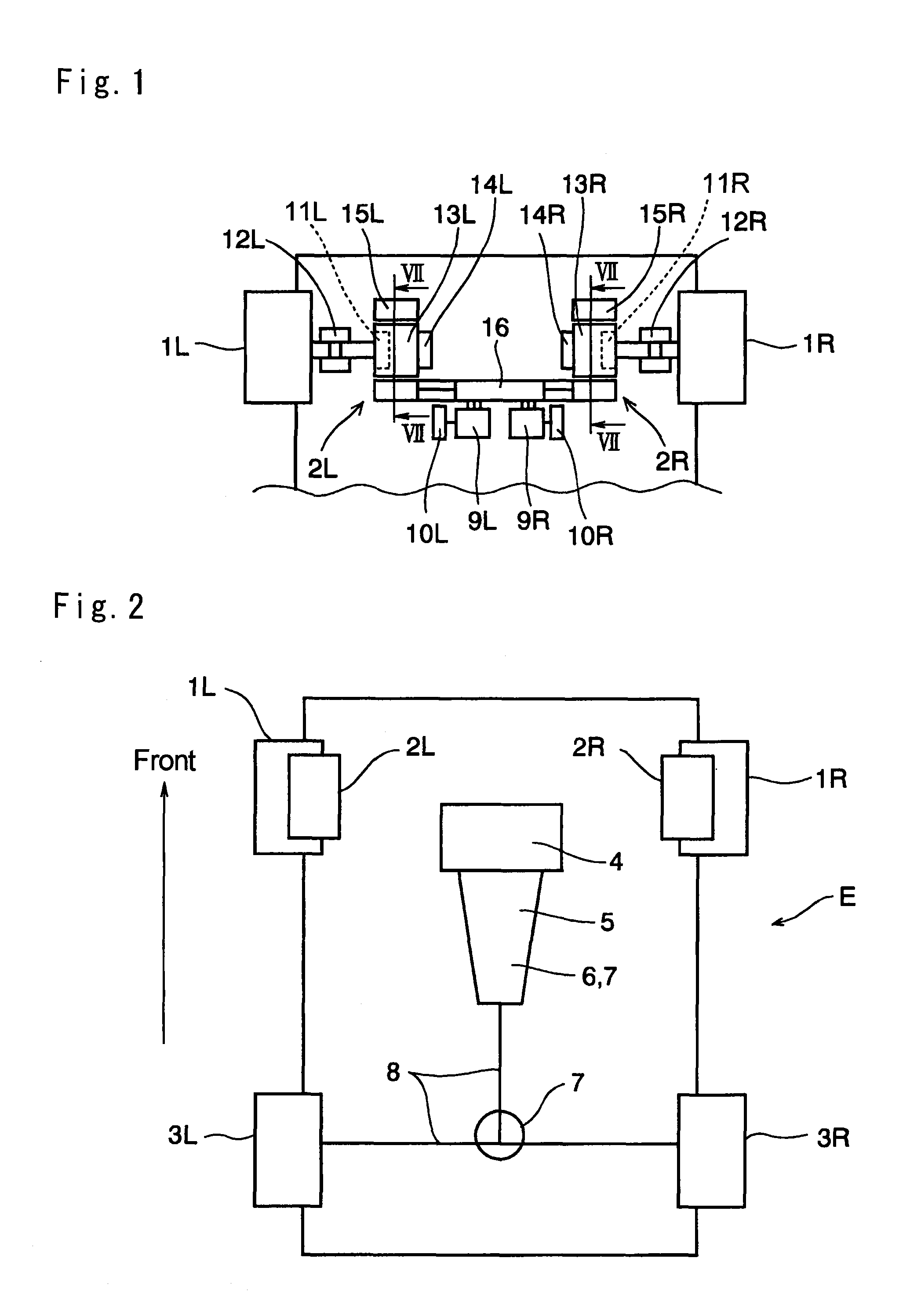
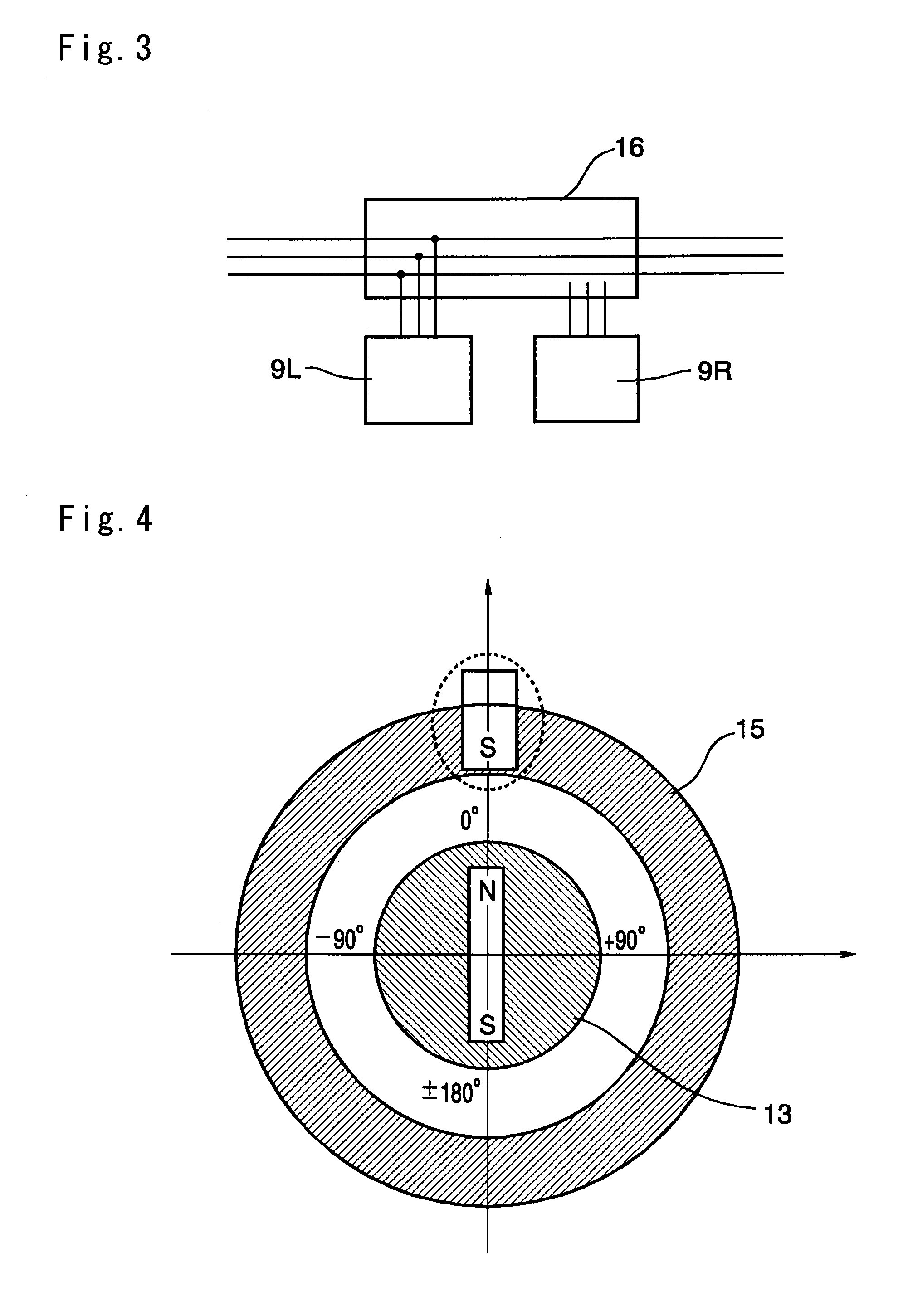
[0025]Next, the present invention will be explained in more detail. The present invention is applied to an automobile having in-wheel motors arranged individually in right and left wheels. For example, the control system of the present invention can be applied not only to a vehicle in which one of the pairs of front and right wheels are driven by the in-wheel motors and the other pairs of wheels are driven by an engine or rotated freely, but also to a vehicle in which all of the wheels are driven by the in-wheel motors. In those kinds of vehicles, a high-efficiency motor is required. Therefore, a permanent magnet synchronous motor is basically used in those kinds of vehicles. Specifically, such permanent magnet synchronous motor comprises a rotor having permanent magnets, and a stator having coils that individually generate a magnetic field when the current is supplied thereto. In case of driving the vehicle, the current is supplied to the coil based on a phase of the rotor in a man...


PUM


Abstract

A control system for driving motor configured to synchronize rotor phases of a plurality of driving motors of wheels using a single inverter. The control system comprises driving motor connected with a wheel to drive the wheel; a clutch interposed between the driving motor and the wheel; and a current control means connected with the driving motor to supply current thereto. A switching unit switches electrical connection in a manner to supply the current to both of the driving motors from one of the current control unit by interrupting the current supply from the other current control unit. The clutch interrupts torque transmission in case the switching mechanism switches the electrical connection in a manner to supply the current to both of the driving motors from one of the current control unit to drive the vehicle.

Description

TECHNICAL FIELD[0001]This invention relates, in general, to a control system for controlling a driving motor of a vehicle, and more particularly, to a control system for a plurality of synchronous motors connected with each wheel of a vehicle.BACKGROUND ART[0002]Driving motors have been used as a prime mover not only in an electric vehicle but also in a hybrid vehicle using both an internal combustion engine and an electric motor. In the electric vehicle, the driving motors are arranged to drive each front wheel or each rear wheel. Alternatively, the driving motors may also be arranged to drive all wheels. Thus, in those kinds of vehicles, the driving motors are provided to drive the right wheel and the left wheel individually. Therefore, if one of those driving motors is in trouble, or if one of electric current sources is in trouble, the driving force of the right and the left wheels lose their balance.[0003]Japanese Patent Laid-Open No. 4-145810 discloses an electric motor vehicl...

Claims


Application Information

Patent Timeline
Patent Type & Authority Patents(United States)
IPC IPC(8): H02P15/00
CPCB60K7/0007B60L11/14B60L11/18B60W10/02B60W10/08B60W50/023H02P5/74B60K17/356Y10T477/6418B60K2007/0046B60K2007/0092B60L2220/44B60L2260/28Y02T10/646Y02T10/7005Y02T10/7077Y02T10/7258B60K1/04B60K17/043B60K17/26B60K2007/0038B60Y2400/61Y02T10/648Y02T10/70Y10T477/26Y10T477/32B60K17/02B60L50/16B60L15/2036B60L50/60Y02T10/72Y02T10/64Y02T10/7072
Inventor ARAKAWA, KAZUYAYOSHIZUE, KENSUKE
Owner TOYOTA JIDOSHA KK
Why Eureka
Try Eureka