Rotating torque transmission buffered shaft

a transmission buffer and rotating torque technology, applied in the direction of shock absorbers, couplings, transportation and packaging, etc., can solve the problems of unbalanced torque value, unbalanced torque value, unusual noise and vibration of cars, etc., to reduce the degree of vehicle vibration, reduce the degree of gear shifting and simple structure

Active Publication Date: 2014-06-26
KUO HER IND +2
View PDF5 Cites 0 Cited by
  • Summary
  • Abstract
  • Description
  • Claims
  • Application Information

AI Technical Summary

Benefits of technology

[0006]The main object of the invention is to provide a rotating torque transmission buffere...

Problems solved by technology

Once the part of the transmission shaft is damaged, worn, deformed, and loss of dynamic balance can cause the car to make unusual noise and vibration while in driving.
In worse cases, such condition can lead to damage to relevant parts.
However, when a vehicle is travelling, changing gear or moving al...

Method used


Image

  • Rotating torque transmission buffered shaft
  • Rotating torque transmission buffered shaft
  • Rotating torque transmission buffered shaft

Examples


Embodiment Construction

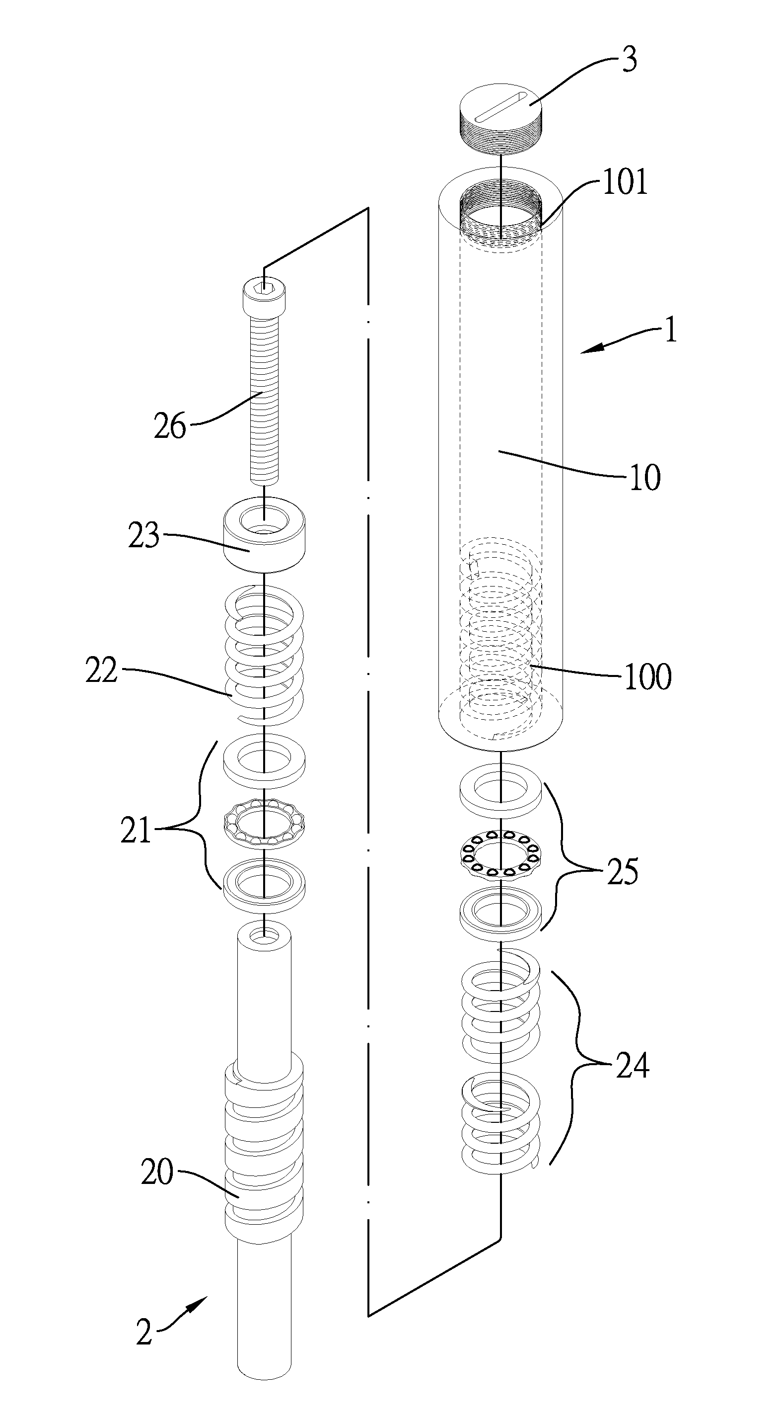
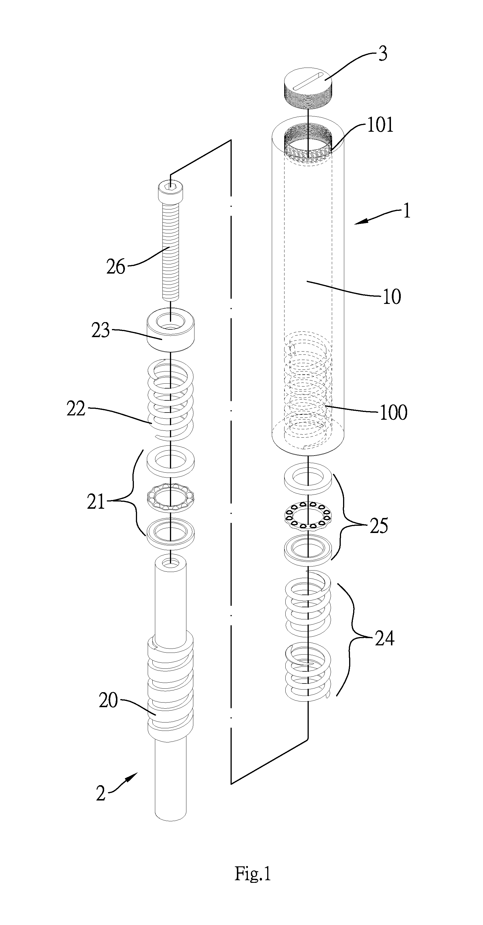
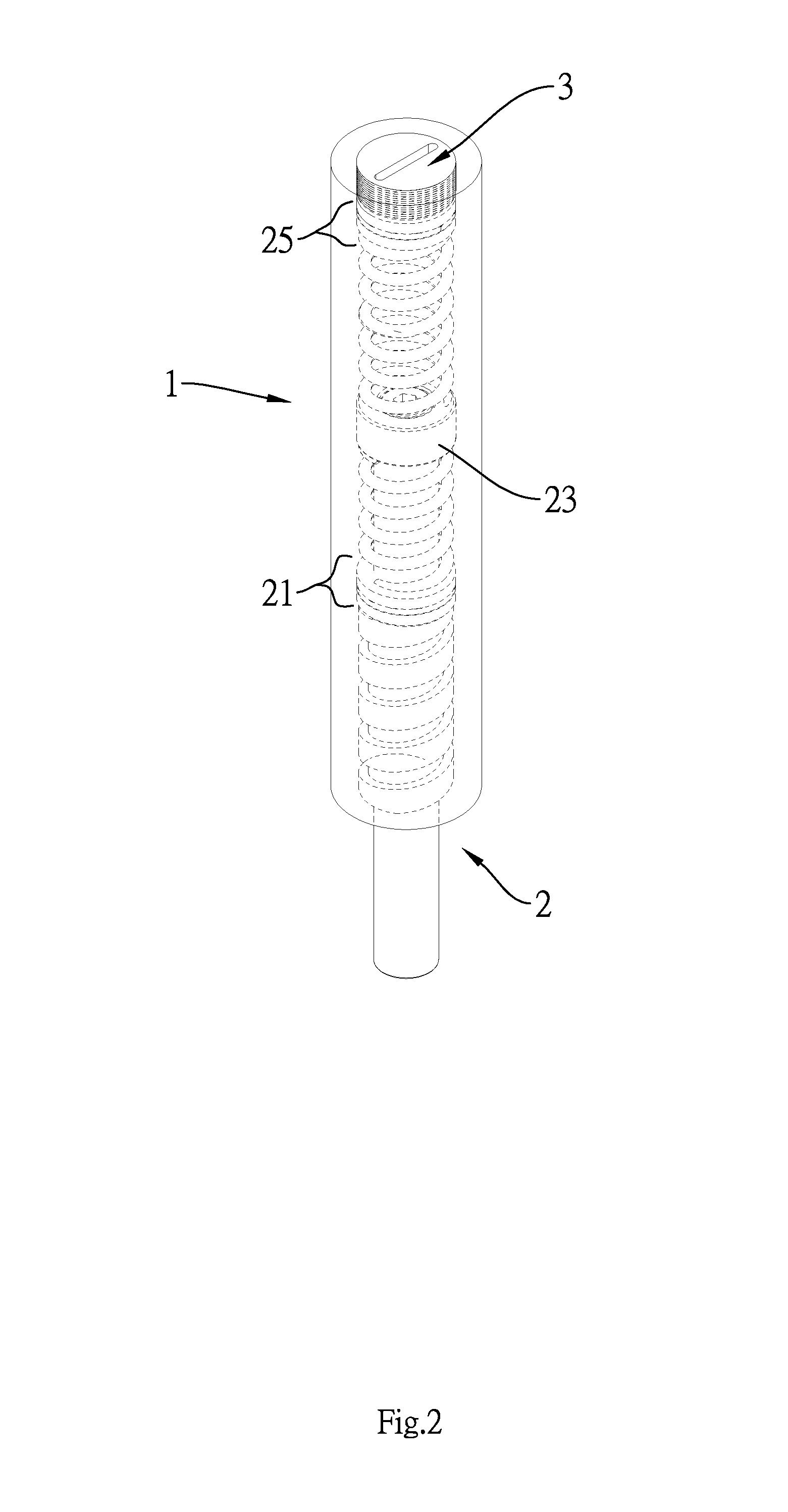
[0019]First, with reference to FIG. 1 and FIG. 2, according to the figures, the rotating torque transmission buffered shaft of the invention comprises a casing tube 1, a shaft tube 2 and a lock mounting member 3.

[0020]The casing tube 1 has a receiving space 10, wherein a first inner screw thread 100 and a second inner screw thread 101 are formed on the inner surface at both ends of the casing tube 1 separately. A second spring body 24 and a second ball bearing 25 are connected to each other and installed inside the receiving space 10.

[0021]One end of the shaft tube 2 is installed inside the receiving space 10 and a screw thread portion 20 corresponding to the first inner screw thread 100 is formed in the middle section of the shaft tube 2. The portion of the shaft tube 2 located inside the receiving space 10 is sleeved with a first ball bearing 21 and a first spring body 22 in sequence, and is locked with a mounting member 23 at the end of the shaft tube 2 in order to make the first...


PUM


Abstract

A rotating torque transmission buffered shaft is provided with a casing tube, a shaft tube and a lock mounting member. The casing tube is formed with a receiving space and the inner walls of both ends of the casing tube are formed with a first inner screw thread and a second inner screw thread respectively. The shaft tube is installed within the receiving space and the middle section of the shaft tube is formed with a screw thread portion corresponding to the first inner screw thread. The lock mounting member is engaged and locked on the second inner screw thread. The rotating torque transmission buffered shaft is applicable to ships and vehicles for public transportation. The buffered shaft can absorb and balance intense rotating torque generated instantly, and can reduce the torque difference generated during the operation due to the linkage between the engine and the transmission device.

Description

BACKGROUND OF THE INVENTION[0001]1. Field of the Invention[0002]The invention relates to buffered shafts and more particularly to a rotating torque transmission buffered shaft which can transmit the torque force, generated from the power output of a vehicle or an engine through a gearbox or an automatic transmission device, to roll or rotate the tires.[0003]2. Description of Related Art[0004]According to the fact, regardless what the form to install an engine and driving wheels is, there must be a complete transmission line, namely a transmission shaft, between the engine and the engine-driven wheels in order to output the power of an engine to the wheels through the clutch, gearbox, transmission shaft, transmission assembly, and finally axle beam, that makes the tires to rotate and thus to drive the vehicle. Once the part of the transmission shaft is damaged, worn, deformed, and loss of dynamic balance can cause the car to make unusual noise and vibration while in driving. In worse...

Claims


Application Information

Patent Timeline
IPC IPC(8): F16C1/02
CPCF16F7/00F16D3/12F16D3/72F16D1/12B60K17/00F16D3/08
Inventor CHU, FENG-SUNG
Owner KUO HER IND
Why Eureka
Try Eureka