Tapping machine for processing end part of hydraulic oil cylinder

A technology of end treatment and hydraulic cylinder, which is applied in the field of hydraulic cylinder processing, can solve the problems of reducing practicability, injuring staff, affecting the support strength of the body, etc., and achieves the effect of improving work efficiency and saving the time for shutting down and installing hydraulic cylinders

Active Publication Date: 2022-07-22
徐州金鼎恒立液压件有限公司
View PDF11 Cites 1 Cited by
  • Summary
  • Abstract
  • Description
  • Claims
  • Application Information

AI Technical Summary

Problems solved by technology

[0003]1. When using the tapping machine, you need to position the hydraulic cylinder first, then start the tapping machine and use the gear box to move down to align with the hole on the end face of the cylinder Tapping is performed, but the end of the hydraulic cylinder is generally a circle of holes, so that it needs to be repositioned to tap a hole, but this is time-consuming and laborious. At the same time, the tapping position of the tapping machine is fixed, which also reduces the understand its practicality;
[0004]2. When using the tap to tap the thread, it will drive the entire gearbox assembly to move downward, so that the whole gearbox will be driven up and down continuously during use, resulting in Its fatigue friction affects the support strength of the machine body. On the other hand, tapping the thread in this way also needs to provide the force for its up and down movement, which is more wasteful in terms of energy consumption;
[0005]3. When tapping the thread, the tap rotates continuously and moves downward, and when drilling into the hydraulic cylinder, the torque on the tap increases with the depth The larger it is, the larger the torque will easily cause the tap to break during the drilling process. If the damage is mild, it needs to be replaced with a new one, and if it is severe, it will cause it to collapse and injure the staff. Generally speaking, it is not conducive to long-term and safe use.

Method used


Image

  • Tapping machine for processing end part of hydraulic oil cylinder
  • Tapping machine for processing end part of hydraulic oil cylinder
  • Tapping machine for processing end part of hydraulic oil cylinder

Examples


Embodiment Construction

[0028] The technical solutions in the embodiments of the present invention will be clearly and completely described below with reference to the accompanying drawings in the embodiments of the present invention. Obviously, the described embodiments are only a part of the embodiments of the present invention, but not all of the embodiments. Based on the embodiments of the present invention, all other embodiments obtained by those of ordinary skill in the art without creative efforts shall fall within the protection scope of the present invention.

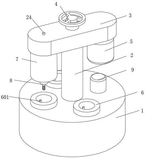
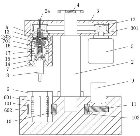
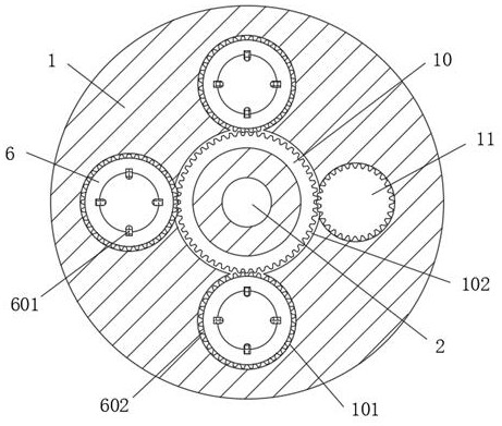
[0029] Please see attached figure 1 , attached figure 2 , attached image 3 , a tapping machine for end treatment of a hydraulic cylinder, comprising a base 1, a rotating shaft 2 is movably installed in the middle of the top surface of the base 1, a transmission box 3 is fixedly installed on the top of the rotating shaft 2, and the middle of the top surface of the transmission box 3 is fixed A runner 4 is installed, a drive motor 5...


PUM


Abstract

The invention relates to the technical field of hydraulic oil cylinder machining, and discloses a tapping machine for hydraulic oil cylinder end treatment, three sleeve holes are formed, positioning cylinders are movably sleeved with the sleeve holes, a transmission gear ring is movably sleeved with a transmission groove, and a driving gear in meshing transmission with the transmission gear ring is fixedly connected to the position, located at the bottom of a control motor, in a base. The upper half portion of the cylindrical groove is movably sleeved with a first transmission sleeve, a limiting hole is formed in the bottom of the first transmission sleeve, the first transmission sleeve is movably sleeved with the top of a second transmission sleeve, transmission connecting rods are movably installed on the first transmission sleeve and the second transmission sleeve in the movable groove in a vertically symmetrical mode, and a hinge device is movably connected between the two transmission connecting rods in the movable groove. Through the design of the positioning cylinder, the transmission sleeve, the hinge device and the like, the tapping machine is more convenient to use, meanwhile, the safety is high, and the service life is longer.

Description

technical field [0001] The invention relates to the technical field of hydraulic oil cylinder processing, in particular to a tapping machine used for processing the end of a hydraulic oil cylinder. Background technique [0002] Hydraulic cylinder is a hydraulic actuator that converts hydraulic energy into mechanical energy and performs linear reciprocating motion. Because it uses high hydraulic pressure, it is also used in many important mechanical equipment. Therefore, the production of hydraulic cylinders needs to ensure quality. Among them After drilling the end of the hydraulic cylinder, it is necessary to tap the thread. Generally, a tapping machine is used. The working principle of the tapping machine is simple: that is, the tap is rotated by the motor drive, and then the tap is aligned with the positioned workpiece. The wire machine has been widely used, but it still has some shortcomings: [0003] 1. When using the tapping machine, it is necessary to position the hy...

Claims


Application Information

Patent Timeline
Patent Type & Authority Applications(China)
IPC IPC(8): B23G1/00B23G1/44
CPCB23G1/00B23G1/44
Inventor 孙兆勇陈浩陈宁魏兴雷
Owner 徐州金鼎恒立液压件有限公司
Why Eureka
Try Eureka