A power configuration method, user equipment and base station
A power configuration and user equipment technology, applied in the field of communication, can solve the problems of unguaranteed information power distribution and unreasonable power distribution.
- Summary
- Abstract
- Description
- Claims
- Application Information
AI Technical Summary
Problems solved by technology
Method used
Image
Examples
Embodiment 1
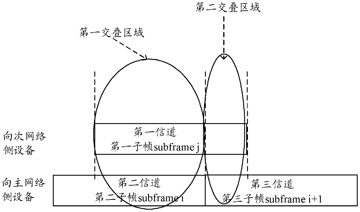
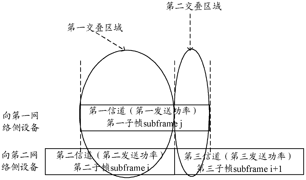
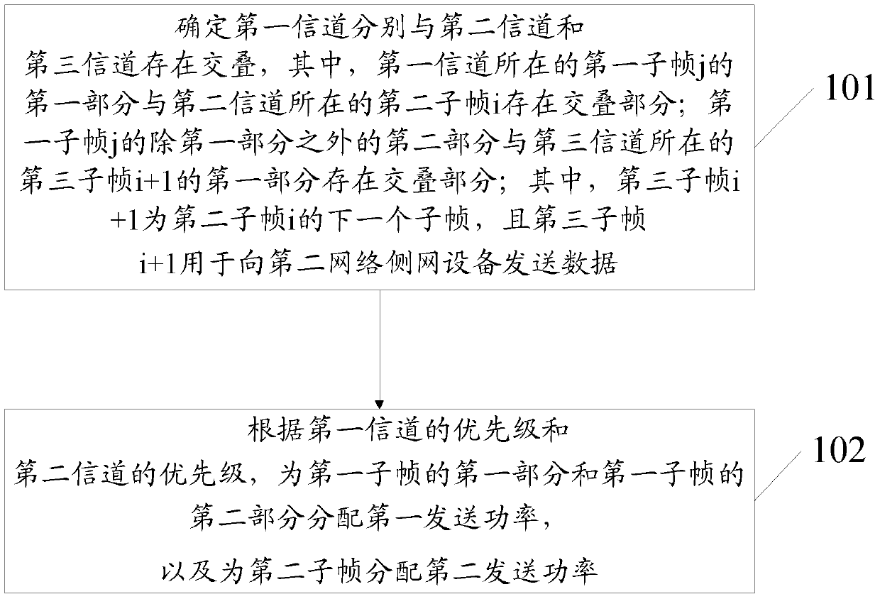
[0127] When the user equipment UE sends data to the first network-side device through the first channel and the UE sends data to the second network-side device through the second channel, this embodiment provides a power configuration method, please refer to figure 2 with image 3 as shown, figure 2 It is a schematic diagram of overlap between channels in the power configuration method of this embodiment; image 3 It is a flow chart of the power configuration method in this embodiment, and the method includes the following contents.
[0128] Step 101: Determine that the first channel overlaps with the second channel and the third channel respectively, wherein the first part of the first subframe j where the first channel is located overlaps with the second subframe i where the second channel is located ; There is an overlap between the second part of the first subframe j except the first part and the first part of the third subframe i+1 where the third channel is located; ...
no. 1 approach
[0171] The first implementation mode: In this implementation mode, please refer to figure 2 As shown, the allocation of power to the first subframe j and the second subframe i is taken as an example, and only the power requirement of the third subframe i+1 is referred to for description.
[0172] First, the UE determines through step 101 that the first channel overlaps with the second channel and the third channel respectively.
[0173] Secondly, the UE determines the transmit power of the first part of the third subframe i+1 according to the priority of the first channel and the priority of the third channel, because only the third subframe i+1 is considered, so the third subframe i The transmission power of the first part of +1 may be regarded as the third transmission power of the third subframe i+1.
[0174] Again, the UE determines the first power upper limit value according to the third transmit power and the second threshold, and the sum of the third transmit power an...
no. 2 approach
[0176] The second embodiment, in this embodiment, please refer to Image 6 As shown, after the UE sends the first subframe j and the second subframe i, the third subframe i+1 and the fourth subframe j+1 are to be sent next, and the subframe to be referred to is the fifth channel The fifth subframe i+2 of . In this case, the process of allocating power for the third subframe i+1 and the fourth subframe j+1 is basically the same as the process of allocating power for the second subframe i and the first subframe j in the first embodiment , the same part will not be repeated here. The difference is that in the process of allocating power for the second subframe i and the first subframe j, the third transmission power is determined for the third subframe i+1, and the third transmission power is the third subframe i+ The pre-transmission power of 1, so when allocating the real transmission power for the third subframe i+1, the pre-transmission power of the third subframe i+1 shoul...
PUM
 Abstract
Description
Claims
Application Information
 - R&D
- Intellectual Property
- Life Sciences
- Materials
- Tech Scout
- Unparalleled Data Quality
- Higher Quality Content
- 60% Fewer Hallucinations
Browse by: Latest US Patents, China's latest patents, Technical Efficacy Thesaurus, Application Domain, Technology Topic, Popular Technical Reports.
© 2025 PatSnap. All rights reserved.Legal|Privacy policy|Modern Slavery Act Transparency Statement|Sitemap|About US| Contact US: help@patsnap.com


