Power configuration method, user equipment and base station

A power allocation and power technology, applied in the field of communication, can solve the problems of unguaranteed information power allocation and unreasonable power allocation.

Pending Publication Date: 2019-09-20
HUAWEI TECH CO LTD
View PDF0 Cites 3 Cited by
  • Summary
  • Abstract
  • Description
  • Claims
  • Application Information

AI Technical Summary

Problems solved by technology

[0008] The present application provides a power configuration method, user equipment and base station, which are used to solve the unreasonable power allocation when the user equipment transmits data on multiple channels in the prior art, which leads to the unguaranteed power allocation of important information question

Method used


Image

  • Power configuration method, user equipment and base station
  • Power configuration method, user equipment and base station
  • Power configuration method, user equipment and base station

Examples


Embodiment 1

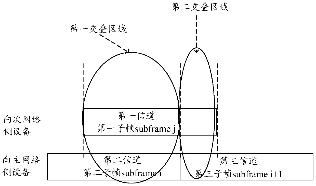
[0127] When the user equipment UE sends data to the first network-side device through the first channel and the UE sends data to the second network-side device through the second channel, this embodiment provides a power configuration method, please refer to figure 2 with image 3 as shown, figure 2 It is a schematic diagram of overlap between channels in the power allocation method of this embodiment; image 3 It is a flow chart of the power configuration method in this embodiment, and the method includes the following contents.

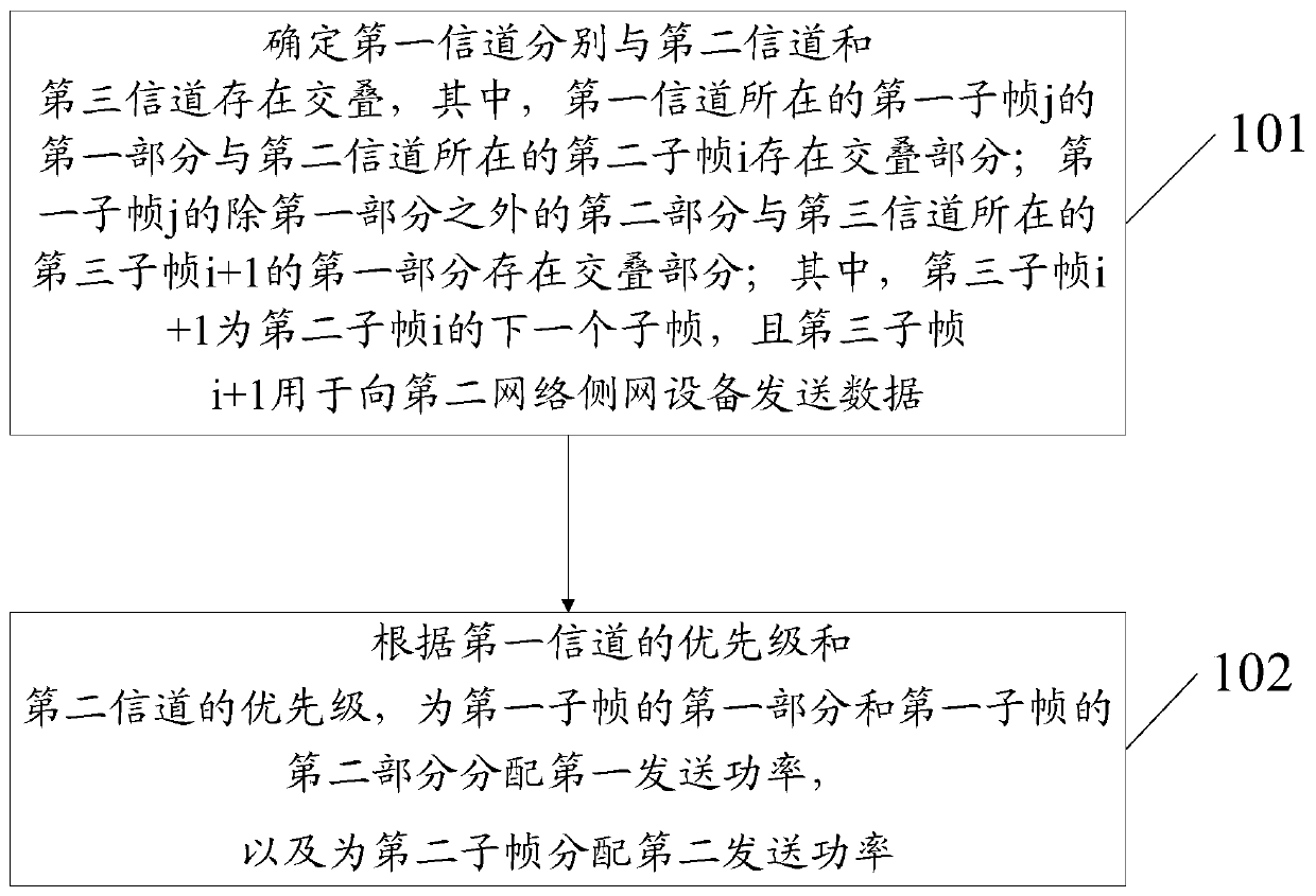
[0128] Step 101: Determine that the first channel overlaps with the second channel and the third channel respectively, wherein the first part of the first subframe j where the first channel is located overlaps with the second subframe i where the second channel is located ; There is an overlap between the second part of the first subframe j except the first part and the first part of the third subframe i+1 where the third channel is located; whe...

no. 1 approach

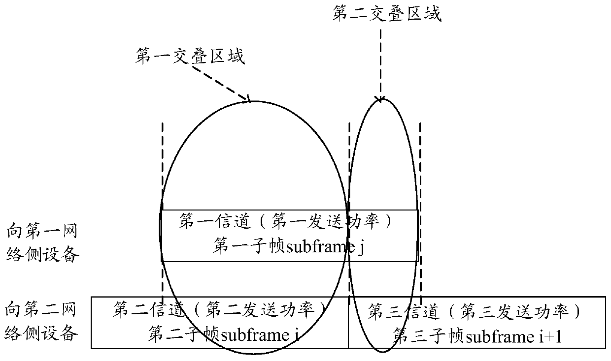
[0171] The first implementation mode: In this implementation mode, please refer to figure 2 As shown, the allocation of power to the first subframe j and the second subframe i is taken as an example, and only the power requirement of the third subframe i+1 is referred to for description.

[0172] First, the UE determines through step 101 that the first channel overlaps with the second channel and the third channel respectively.

[0173] Secondly, the UE determines the transmit power of the first part of the third subframe i+1 according to the priority of the first channel and the priority of the third channel, because only the third subframe i+1 is considered, so the third subframe i The transmission power of the first part of +1 may be regarded as the third transmission power of the third subframe i+1.

[0174] Again, the UE determines the first power upper limit value according to the third transmit power and the second threshold, and the sum of the third transmit power an...

no. 2 approach

[0176] The second embodiment, in this embodiment, please refer to Image 6 As shown, after the UE sends the first subframe j and the second subframe i, the third subframe i+1 and the fourth subframe j+1 are to be sent next, and the subframe to be referred to is the fifth channel The fifth subframe i+2 of . In this case, the process of allocating power for the third subframe i+1 and the fourth subframe j+1 is basically the same as the process of allocating power for the second subframe i and the first subframe j in the first embodiment , the same part will not be repeated here. The difference is that in the process of allocating power for the second subframe i and the first subframe j, the third transmission power is determined for the third subframe i+1, and the third transmission power is the third subframe i+ The pre-transmission power of 1, so when allocating the real transmission power for the third subframe i+1, the pre-transmission power of the third subframe i+1 shoul...


PUM


Abstract

The invention provides a power configuration method and device. The method comprises the steps that when UE sends data to first network side equipment from a first channel and sends data to second network side equipment from a second channel, it is determined that the first channel is overlapped with the second channel and a third channel, and a first part of a first sub-frame j where the first channel is located is overlapped with a second sub-frame i where the second channel is located; the second part, except the first part, of the first sub-frame j is overlapped with the first part, where the third channel is located, of the third sub-frame i + 1; wherein the third sub-frame i + 1 is the next sub-frame of the second sub-frame i; according to the priorities of the first channel and the second channel, allocating first transmitting power to the first sub-frame j and allocating second transmitting power to the second sub-frame i, wherein the first transmitting power is less than or equal to the first power upper limit value, the sum of the first transmitting power and the second transmitting power is less than or equal to the first threshold value, and the sum of the third transmitting power of the third subframe i + 1 and the first power upper limit value is less than or equal to the second threshold value.

Description

technical field [0001] The present application relates to the field of communication technology, and in particular to a power configuration method, user equipment and base station. Background technique [0002] LTE-A (Long Term Evolution-Advanced; Advanced Long Term Evolution) is a further evolution and enhanced system of the 3GPP LTE system. In the LTE-A system, CA (Carrier Aggregation) technology is introduced to meet the peak data rate requirements of the International Telecommunication Union for the fourth-generation communication technology. In carrier aggregation, the frequency spectrum of two or more component carriers (ComponentCarrier) is aggregated together to obtain a wider transmission bandwidth. Adjacent spectrum or even discontinuous spectrum in different frequency bands. LTE-A user equipment can simultaneously access multiple component carriers for data transmission and reception according to its capabilities and service requirements. [0003] In the subseq...

Claims


Application Information

Patent Timeline
Patent Type & Authority Applications(China)
IPC IPC(8): H04W52/28H04W52/34H04W52/36H04W52/40H04W72/04
CPCH04W52/243H04W52/281H04W52/40H04W72/0446H04W52/367H04W72/56H04W72/541H04W52/34H04W52/346H04B7/024
Inventor 邵家枫曲秉玉李强
Owner HUAWEI TECH CO LTD
Why Eureka
Try Eureka