A driving system of an electronic track intelligent train and a power distribution method thereof

A technology of drive system and electronic track, which is applied in the field of rail transit, can solve problems such as unsatisfactory demand, achieve sufficient power, good economy, and improve vehicle dynamics

Active Publication Date: 2018-12-11
CHENGDU XINZHU ROAD & BRIDGE MASCH CO LTD
View PDF9 Cites 4 Cited by
  • Summary
  • Abstract
  • Description
  • Claims
  • Application Information

AI Technical Summary

Problems solved by technology

Traditional driving methods and power di...

Method used


Image

  • A driving system of an electronic track intelligent train and a power distribution method thereof
  • A driving system of an electronic track intelligent train and a power distribution method thereof
  • A driving system of an electronic track intelligent train and a power distribution method thereof

Examples


Embodiment 1

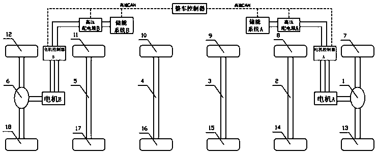
[0027] Such as figure 1 As shown, an electronic track intelligent train driving system includes a driving system A, a driving system B, a driving shaft A1, a driving shaft B6, a plurality of steering shafts 2 to 5, and two shafts (each driving shaft and each steering shaft) The rubber wheels 7-18 at the end, the drive system A is composed of a motor A, a motor controller A, a high-voltage distribution box A, and an energy storage system A connected in sequence, the motor A drives the drive shaft A1, and the drive system B is composed of Connected motor B, motor controller B, high-voltage distribution box B, and energy storage system B, motor B drives the drive shaft B6, and the CAN network of the drive system A and drive system B is connected to the vehicle controller. communication. The vehicle controller collects the data of vehicle speed, accelerator pedal and brake pedal to realize unified coordination, control and reasonable power distribution.

Embodiment 2

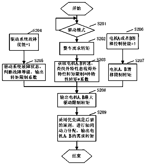
[0029] A power distribution method of an electronic track intelligent train drive system, such as figure 2 shown, including the following steps:

[0030] In the first step, the vehicle controller judges whether the vehicle is in the driving mode, and if it is in the driving mode, obtains and outputs the required torque of the vehicle according to the required torque MAP. The vehicle controller collects the state parameters of gear position, accelerator pedal, brake pedal and handbrake, and uses these state parameters to determine whether the vehicle is in the driving mode.

[0031] In the second step, according to the maximum drive limit torque of the motor, the power distribution is performed on the torque between the shafts, and the required torque of the motor is output to realize cooperative control. The maximum drive limit torque of the motor = min (external characteristic limit torque * drive system torque limit coefficient, slip limit torque); check the external chara...


PUM


Abstract

The invention discloses an electronic track intelligent train driving system, which includes a drive system A, a drive System B, a drive shaft A, a drive shaft B, a number of steering shafts and rubber wheels at both ends of each shaft, the drive system A is composed of a motor A, a motor controller A, a high-voltage distribution box A and the energy storage system A connected in turn; a motor A drives a driving shaft A; a motor B, a motor controller B, a high-voltage distribution box B and an energy storage system B are connected in turn to form the drive system B. The motor B drives the driving shaft B, and the CAN network of the driving system A and the driving system B communicates with the whole vehicle controller. A symmetrical arrangement, redundancy design and centralize direct drive mode of permanent magnet synchronous motor are adopted in that invention. When one drive system can not work, a single drive system can be used to meet the requirement of most working conditions, and the invention is suitable for bi-directional train driving, and has the characteristic of reasonable axle load distribution of the vehicle, sufficient power, safety, reliability and good economy.

Description

technical field [0001] The invention relates to a drive system, in particular to a drive system for an electronic rail intelligent train, and also provides a power distribution method matched with the drive system, which belongs to the technical field of rail transportation. Background technique [0002] With the development of society and the rapid expansion of cities, large and medium-sized cities have problems such as low passenger travel efficiency and poor comfort in urban public transportation due to dense population and resource constraints. The electronic rail smart train is a fusion product of trams and electric buses. It not only combines the characteristics of trams with no pollution, fast speed, and large capacity, but also absorbs the characteristics of flexible operation of traditional buses. It has strong comprehensive transport capacity and short construction period. Short, intelligent network connection and other advantages, has a good development prospect. ...

Claims


Application Information

Patent Timeline
IPC IPC(8): B60L15/20B60L3/00
CPCB60L3/0023B60L15/20B60L2200/26B60L2240/423Y02T10/72
Inventor 程静张永俊刘强陈飞飞田野
Owner CHENGDU XINZHU ROAD & BRIDGE MASCH CO LTD
Why Eureka
Try Eureka