Lower riveting head rivet pulling device and full-automatic binding machine

A technology of riveting head and switching device, which is applied in the field of binding machines, can solve the problems of inaccurate positioning, unstable production cost, complex structure, etc., and achieve the effect of stable transmission and simple and reasonable linkage structure

Active Publication Date: 2016-01-27
DELI GROUP CO LTD
View PDF9 Cites 17 Cited by
  • Summary
  • Abstract
  • Description
  • Claims
  • Application Information

AI Technical Summary

Problems solved by technology

The structure is relatively complex, the positioning is not accurate, and there are disadvantages of instability and high production costs.

Method used


Image

  • Lower riveting head rivet pulling device and full-automatic binding machine
  • Lower riveting head rivet pulling device and full-automatic binding machine
  • Lower riveting head rivet pulling device and full-automatic binding machine

Examples


Embodiment Construction

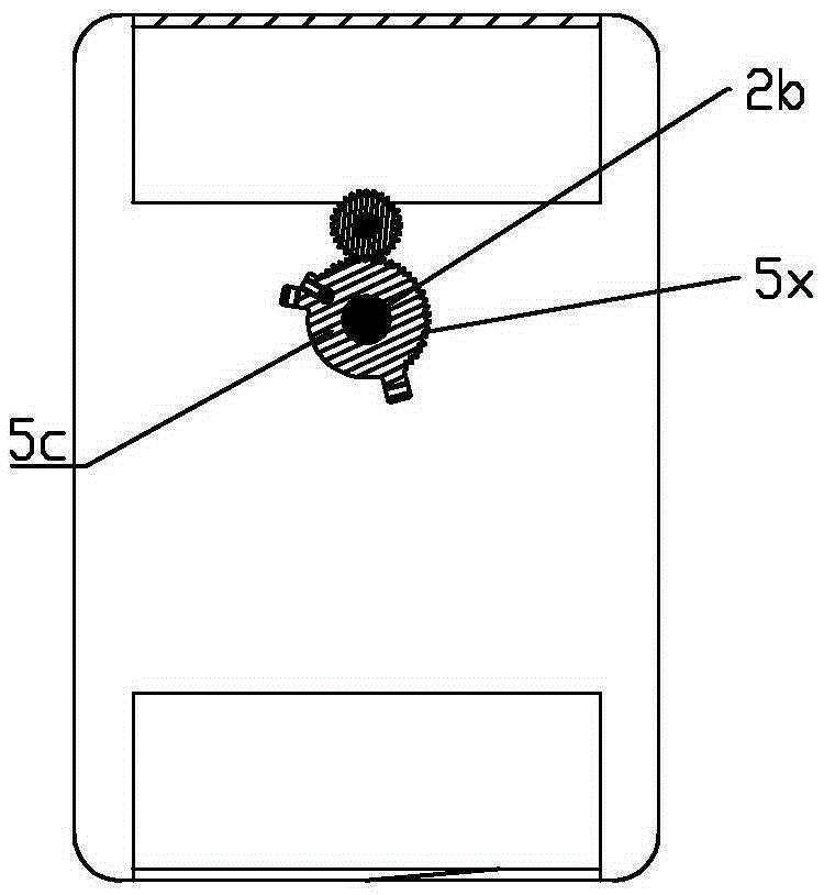
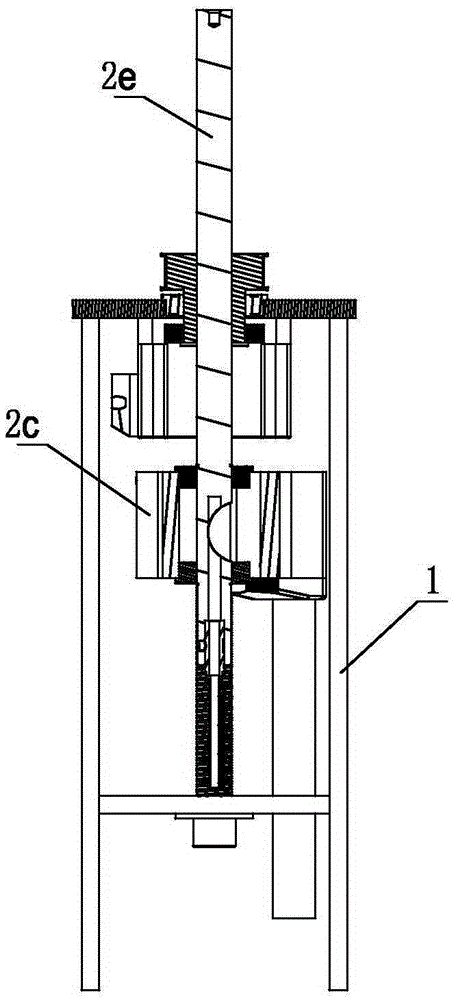
[0088] Such as Figure 1 to Figure 47 As shown, a lower riveting head riveting device includes a first motor 2d in a frame 1, a lifting seat 2c, a vertical guide post 2b, a lower riveting head 5b and a switching device, and the lifting seat 2c is positioned on the vertical guide post The upper part of 2b is moved vertically by the first motor 2d, the lower riveting head 5b is set on the switching device, and can be moved horizontally and vertically through the switching device, and a vertical riveting rod is arranged between the lifting seat 2c and the switching device 5a, when the lifting base 2c rises, pull the switching device to move vertically upwards.

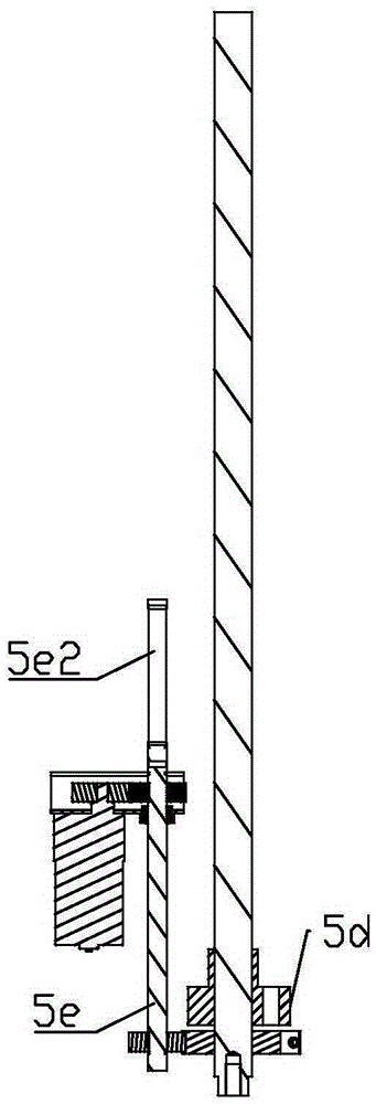
[0089] The switching device includes a switching base 5c, a first switching block 5d and a second motor 1b, the first switching block 5d and the switching base 5c are rotatably positioned at the bottom of the vertical guide column 2b, and the first switching block 5d can be lifted and positioned on the switching On the b...


PUM


Abstract

The invention relates to a lower riveting head rivet pulling device and a full-automatic binding machine. The lower riveting head rivet pulling device comprises a first motor, a lifting base, a vertical guide column, a lower riveting head and a switchover device, all of which are arranged in a rack. The lifting base is positioned at the upper portion of the vertical guide column and driven by the first motor to vertically ascend and descend. The lower riveting head is arranged on the switchover device and is capable of doing horizontal and vertical movement through the switchover device. A vertical rivet pulling rod is arranged between the lifting base and the switchover device. When the lifting base ascends, the switchover device is pulled to vertically move upwards. The full-automatic lower riveting head rivet pulling device and the full-automatic bonding machine utilizing the drilling lifting base for upward linkage rivet pulling are provided and have the beneficial effects of being simple in structure and reasonable in transmission.

Description

technical field [0001] The invention relates to a binding machine, in particular to a lower riveting head riveting device and a fully automatic binding machine. Background technique [0002] The traditional automatic punching and hot riveting binding machine includes the upper automatic punching device and the lower hot riveting device on the working table, which realizes automatic punching of the binding object, measuring and cutting and sending the riveting tube, and the hot riveting tube is inserted into the hole and then goes up and down End hot riveting binding and other actions, the traditional automatic punching hot riveting binding machine and the above-mentioned parts have shortcomings such as complex linkage structure and unstable binding quality. During the hot riveting process, it is necessary to heat the lower riveting head upwards and the upper riveting head so that the upper and lower ends of the binding riveting tube form the riveting head to bind the binding...

Claims


Application Information

Patent Timeline
Patent Type & Authority Applications(China)
IPC IPC(8): B42B5/08B42B5/02B42B5/00B26F1/16
Inventor 孙兵
Owner DELI GROUP CO LTD
Why Eureka
Try Eureka