Material conveying device for concrete batching plant

A technology of conveying device and mixing station, which is applied in packaging and other directions, can solve problems such as material blockage and unsmooth conveying, and achieve the effects of avoiding material blockage, improving efficiency, and reducing waste power consumption

Inactive Publication Date: 2016-01-27
马宗刚
View PDF0 Cites 2 Cited by
  • Summary
  • Abstract
  • Description
  • Claims
  • Application Information

AI Technical Summary

Problems solved by technology

[0003] Screw conveyors include those with and without shafts. For screw conveyors with shafts, the spiral blades on the shaft are generally evenly arranged on the shaft. This kind of screw shaft sometimes has the problem of material clogging during the material conveying process. , resulting in unsmooth delivery

Method used


Image

  • Material conveying device for concrete batching plant

Examples


Embodiment Construction

[0012] In order to make the object, technical solution and advantages of the present invention clearer, the present invention will be further described in detail below in conjunction with the accompanying drawings.

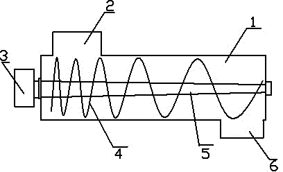
[0013] see figure 1 , a material conveying device for a concrete mixing plant, comprising a material conveying cylinder 1, an inlet 2 and an outlet 6 are arranged on the material conveying cylinder, and a driven The mechanism 3 drives a rotating shaft 5, on which there are several helical blades 4; the pitch between the helical blades gradually increases from the feed end to the discharge end.

[0014] Further, the diameter of the rotating shaft 5 gradually decreases from the feed end to the discharge end.

[0015] The drive mechanism 3 is a speed-regulating motor.

[0016] The material conveying cylinder 1 is provided with a start-stop switch of a speed regulating motor.

[0017] The material conveying device for the concrete mixing plant of the present invent...


PUM


Abstract

The invention discloses a material conveying device for a concrete batching plant. The material conveying device for the concrete batching plant comprises a material conveying barrel. A material inlet and a material outlet are formed in the material conveying barrel. A rotary shaft driven by a driving mechanism to rotate is arranged in the material conveying barrel. A plurality of screw blades are arranged on the rotary shaft. The screw pitches among the screw blades are gradually increased from the material inlet end to the material outlet end. According to the material conveying device for the concrete batching plant, due to the fact that the screw pitches among the screw blades are gradually increased from the material inlet end to the material outlet end, in the conveying process of a material, the material blocking problem caused in the material conveying process can be effectively avoided; the reactive power consumption is reduced. Meanwhile, the conveying of the material is accelerated, and the efficiency is improved.

Description

technical field [0001] The invention relates to a material conveying device, in particular to a material conveying device for a concrete mixing station. Background technique [0002] During the material mixing process of the concrete mixing plant, the relevant materials need to be transported to the mixer for mixing. The current material transport devices include belt conveyors, chain plate conveyors, and screw conveyors. [0003] Screw conveyors include those with and without shafts. For screw conveyors with shafts, the spiral blades on the shaft are generally evenly arranged on the shaft. This kind of screw shaft sometimes has the problem of material clogging during the material conveying process. , resulting in unsmooth transportation. Contents of the invention [0004] The object of the present invention is to provide a material conveying device for a concrete mixing plant that can effectively prevent the clogging of conveyed materials. [0005] To achieve the above ...

Claims


Application Information

Patent Timeline
Patent Type & Authority Applications(China)
IPC IPC(8): B65G33/14B65G33/26
CPCY02P70/10
Inventor 马宗刚
Owner 马宗刚
Why Eureka
Try Eureka