A rolling rotor compressor

A rolling rotor type, compressor technology, applied in the direction of rotary piston type machinery, machine/engine, rotary piston type pump, etc., can solve the problems of roller wear, reduced compressor reliability, high contact stress, etc.

Active Publication Date: 2017-06-09
ZHUHAI GREE REFRIGERATION TECH CENT OF ENERGY SAVING & ENVIRONMENTAL PROTECTION
View PDF5 Cites 0 Cited by
  • Summary
  • Abstract
  • Description
  • Claims
  • Application Information

AI Technical Summary

Problems solved by technology

[0003] The purpose of the present invention is to provide a rolling rotor compressor, which has a radially flexible mechanism to solve the problem of the relationship between the rollers in the pump body, such as the crankshaft and the sliding vane, when the rolling rotor compressor is under severe working conditions or high-speed operation. Excessive local contact stress between other parts, etc. leads to the problem of roller wear and compressor reliability decline

Method used


Image

  • A rolling rotor compressor
  • A rolling rotor compressor
  • A rolling rotor compressor

Examples


Embodiment Construction

[0023] Preferred embodiments of the present invention are described below, and it should be understood that the preferred embodiments described here are only used to illustrate and explain the present invention, and are not intended to limit the present invention.

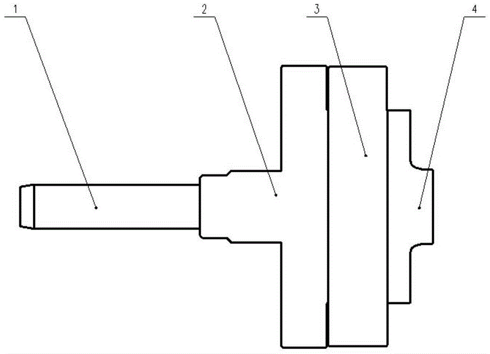
[0024] The following embodiments of the present invention are applicable to rolling rotor compressors having one or more working chambers. figure 1 The structure of a pump body (working chamber) of a rolling rotor compressor is shown in . For ease of illustration, Figure 1-Figure 6 The pump body in the table is expressed horizontally, but in practice, the pump body is usually placed vertically. Such as figure 1 As shown, the pump body generally includes a crankshaft 1 , an upper flange 2 , a cylinder 3 , and a lower flange 4 , wherein the cylinder 3 is arranged between the upper flange 1 and the lower flange 2 .

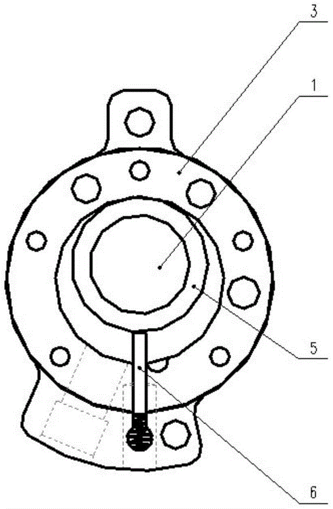
[0025] In the existing technology, such as figure 2 The pump body of the rolling rotor compresso...


PUM


Abstract

The invention provides a rolling rotor compressor, the pump body of which includes a crankshaft, an upper flange, a cylinder, a lower flange, rollers, and slides, and the crankshaft, the rollers, and / or the slides are respectively Or a radial flexible mechanism is provided at the same time. The radial flexible mechanism on the crankshaft is a crescent-shaped flexible groove. The radial flexible mechanism on the roller is an annular flexible groove. The radial flexible mechanism on the slide is a flexible hole. The rolling rotor compressor provided by the invention is provided with a radial flexible mechanism on parts such as crankshafts, rollers and sliding vanes. The position of these radial flexible mechanisms is the contact position / stress concentration position in the working state of the parts. Through its flexible deformation, the local contact stress between the parts can be reduced, or the parts where the stress is concentrated can be transferred, so as to reduce wear and improve the life of the parts. effect and purpose.

Description

technical field [0001] The invention relates to a rolling rotor compressor, in particular to a rolling rotor compressor with a radial flexible mechanism, which belongs to the technical field of air conditioning equipment. Background technique [0002] At present, the rolling rotor compressors used in air conditioners generally adopt a high back pressure design scheme, and the sliding vanes are in contact with the rollers under the action of back pressure (high pressure), so wear occurs during relative motion. When the operating conditions are harsh or high-speed operation, the contact wear between the rollers and other parts such as sliding plates and crankshafts is serious. With the expansion of air-conditioning application fields, especially with the application of air-conditioning systems in high-temperature areas, this problem has become increasingly prominent. In the field of air-conditioning equipment technology, low back pressure design schemes have been proposed to ...

Claims


Application Information

Patent Timeline
Patent Type & Authority Patents(China)
IPC IPC(8): F04C18/356
Inventor 刘靖胡余生魏会军朱红伟王大号
Owner ZHUHAI GREE REFRIGERATION TECH CENT OF ENERGY SAVING & ENVIRONMENTAL PROTECTION
Why Eureka
Try Eureka