

A lever assembly of a ratchet compensation device for an industrial brake
A compensating device and brake technology, applied in the direction of slack adjusters, etc., can solve the problems of heavy brake maintenance workload, fast wear of pawls, hidden dangers of personal and equipment safety, etc., to enhance environmental adaptability, reduce local contact stress, The effect of prolonging the service life
Active Publication Date: 2018-08-10
四川劲兴制动科技有限公司
View PDF7 Cites 0 Cited by
- Summary
- Abstract
- Description
- Claims
- Application Information
AI Technical Summary
Problems solved by technology
However, the pawl currently used in this compensation method relies on the spring to press on the ratchet wheel, and the thickness of the joint between the pawl and the ratchet wheel gradually decreases. Or fragmentation, strength is difficult to guarantee and other problems
The two compensation methods are not ideal at present, resulting in most industrial brakes not equipped with automatic compensation devices for brake pad wear
Due to the large maintenance workload of the brakes without compensation devices, many ground brakes are "decorated" and cannot be put into use; special equipment such as cranes often have unsafe conditions such as sliding hooks and slipping, and frequent braking of the brakes is required. The pull rod is adjusted, which brings safety hazards to personal and equipment
In the utility model patent "An automatic compensation device for industrial drum brakes" (application number: 201320388304.0), the ratchet is moved by a paddle made of thin steel plate. At the same time, taking into account the elastic deformation of the paddle when retreating and the sufficient strength of the paddle when the ratchet is moved, hindering the popularization and application of this patented technology
Method used
View moreImage
Smart ImageViewing Examples

Examples
Embodiment 1
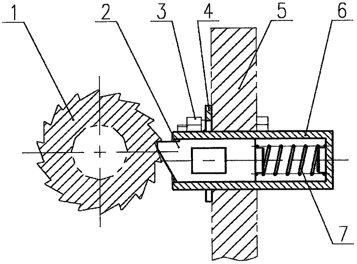
[0030] Embodiment 1: When the present invention is used in an electrohydraulic drum brake, the lever assembly is mounted on a suitable position of the brake lever plate 5, and when the electrohydraulic pusher pushes the brake lever plate 5 to rotate, the lever 2 can be toggled and The ratchet 1 connected to the brake pull rod rotates to realize automatic compensation of brake lining wear.
Embodiment 2
[0031] Embodiment 2: When the present invention is used in an electrohydraulic disc brake, the shift lever assembly is mounted on a proper position of the brake lever plate 5, and its compensation principle is the same as that in Embodiment 1.
Login to View More PUM
 Abstract
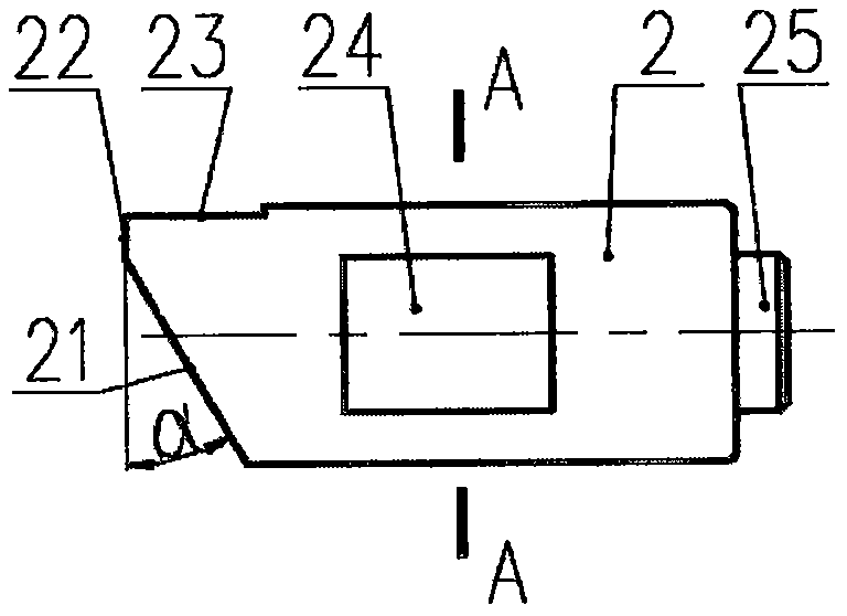
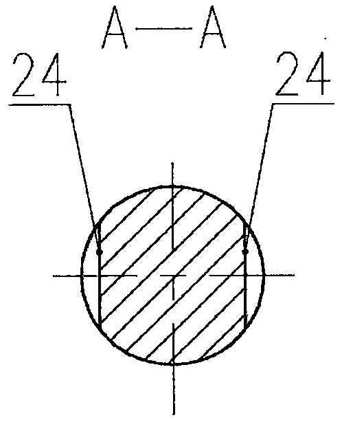
The invention relates to a shift lever assembly of a ratchet type compensating device of an industrial brake. The shift lever assembly is composed of a shift rod 2, a clamping sheet 4, a sleeve 6 and a spring 7. The shift lever assembly is mainly structurally characterized in that the front end of the shift rod 2 is provided with a projection; the projection is composed of an oblique surface 21, a front-end surface 22 and an upper surface 23; the shift rod 2 and the spring 7 are mounted in the hole of the sleeve 6; the shift lever assembly is inserted into the hole of a brake lever plate 5 through the sleeve 6; and furthermore the shift lever assembly is mounted on the brake lever plate 6 through bolt holes 42 of the clamping sheet 4. The shift lever assembly well settles the following severe problems in a ratchet-pawl type compensating device: large partial stress, wearing, fragmentation, deformation, etc. The shift lever assembly of the ratchet type compensating device of an industrial brake has high adaptive capability to an environment and settles a technical problem of incapability of realizing smooth operation of an automatic compensating device for the brake.
Description
technical field [0001] The invention relates to a lever assembly of a ratchet compensation device of an industrial brake. It belongs to the field of mechanical components. Background technique [0002] Industrial brakes are widely used in various lifting, belt transportation, port loading and unloading and metallurgy machinery for deceleration and parking braking of various mechanical transmissions. Due to the wear of the brake lining during the use of the brake, its wear to a certain extent will lead to the failure of the braking function. To solve this problem, one relies on manual frequent maintenance, and the other relies on the use of an automatic compensation device for brake lining wear. At present, the automatic compensation device for brake lining wear includes a one-way bearing method and a ratchet pawl method, both of which are driven by the rotation of the brake lever plate to generate a compensation action. The one-way bearing type compensation device require...
Claims
Login to View More Application Information
Patent Timeline
 Patent Type & AuthorityPatents(China)
IPC IPC(8): F16D65/40
Inventor周兴
Owner四川劲兴制动科技有限公司