
Rolling-element bearing having an oblique running surface section

A technology for rolling bearings and working surfaces, applied in the field of rolling bearings, can solve the problems of insufficient lubricant supply, less support of needle rollers, etc., and achieve the effects of cost saving, size saving, weight saving and material saving

Active Publication Date: 2016-01-27
AB SKF
View PDF9 Cites 0 Cited by
  • Summary
  • Abstract
  • Description
  • Claims
  • Application Information

AI Technical Summary

Problems solved by technology

However, a disadvantage of this prior art is that the needle rollers have only little support in the heavily tapered region of the bearing bearing point.
In addition, an area of ​​the needle roller is permanently covered by the bearing bearing point, so that in this case the covered area can only be insufficiently supplied with lubricant

Method used


Image

  • Rolling-element bearing having an oblique running surface section
  • Rolling-element bearing having an oblique running surface section
  • Rolling-element bearing having an oblique running surface section

Examples


Embodiment Construction

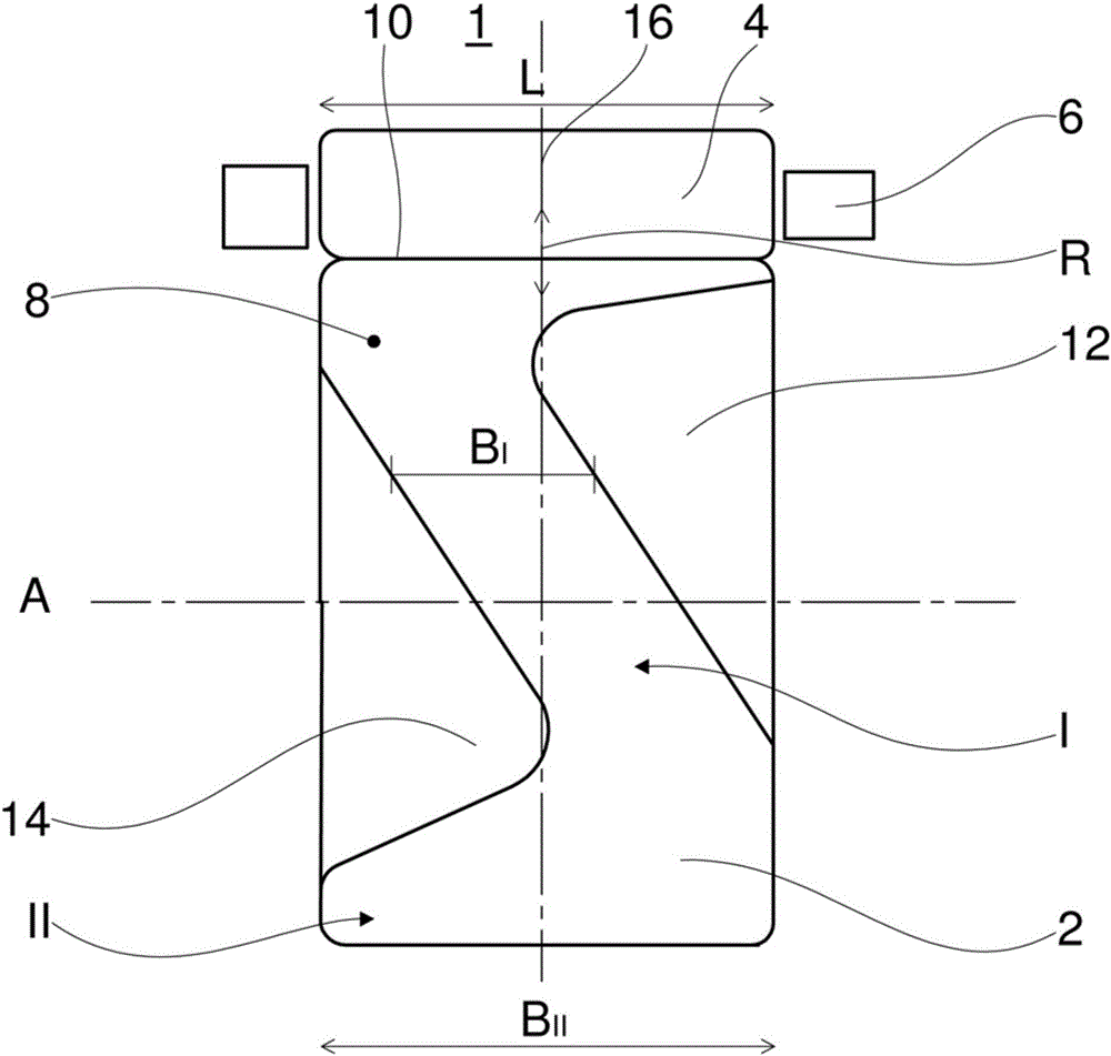
[0024] figure 1 A schematic plan view of the rolling body 1 is shown, but only the inner part 2 therein and the rolling body 4 , which are mounted in the cage 6 . An outer part (not shown) closes the rolling bearing 1 or the rolling bodies 4 radially on the outside. Also in figure 1 As shown in FIG. 1 , the inner part 2 and the not-shown outer part rotate about a common axis of rotation A, whereby the rolling bodies 4 move in a direction R on the inner part 2 . Furthermore, a running surface 8 is formed on the inner part 2 , which contacts the rolling body 4 along a straight line 10 .

[0025] Since the rolling elements 4 are configured in such a way that they contact the running surface 8 of the inner part 2 along a straight line 10 (the so-called contact line), such a rolling bearing 1 is referred to as a rolling bearing with line contact. The rolling elements themselves can have a cylindrical shape, as in the illustrated needle bearing, but it is also possible to use con...


PUM


Abstract

The invention discloses a rolling-element bearing (1) with line contact between a bearing outer part and a bearing inner part (2). The rolling-element bearing with line contact includes the bearing outer part and the bearing inner part, each of which forms a running surface (8) for at least one rolling element (4) disposed between the inner and outer parts. The rolling element (4) contacts these running surfaces (8) along a line (10) when it rolls. Furthermore, the at least one rolling element (4) has an axial rolling-element length (L), the running surface (8) of the bearing outer ring has an axial outer running surface width (B), and the running surface (8) of the bearing inner ring (2) has an axial inner running surface width (B). The outer running surface width (BI) and / or the inner running surface width (BI) is narrower than the rolling-element width (L) in at least a first circumferential partial region (I) of the rolling element, wherein the at least one running surface in the running surface (8) extends obliquely to the rolling direction (R) of the at least one rolling element (4) in the first circumferential partial region (I).

Description

technical field [0001] The invention relates to a rolling bearing having a line contact with a bearing outer part and a bearing inner part, which each form a running surface for at least one rolling body arranged between the bearing outer part and the bearing inner part , where the rolling elements contact the working surface along a straight line when rolling. Background technique [0002] All rolling bearings that are not ball bearings are often referred to as rolling bearings with line contact. Examples of this category are cylindrical roller bearings and tapered roller bearings, as well as radial needle roller bearings or toroidal bearings. However, a disadvantage in rolling bearings with line contact is that the lubricant is often not distributed over the entire length of the rolling elements, so too little lubricant is often present especially in the inner region of the contact line. [0003] From the prior art EP 1775484 a radial needle roller bearing is known, the ...

Claims


Application Information

Patent Timeline
IPC IPC(8): F16C33/46F16C33/58F16C33/66
CPCF16C33/585F16C19/26F16C19/46F16C33/6681F16C2300/02F16F15/267
Inventor R.鲍赫E.古乔恩N.休恩
Owner AB SKF
Learn More