Master cylinder

a technology of master cylinder and master cylinder, which is applied in the direction of rotary clutches, fluid couplings, brake systems, etc., can solve the problems of increasing the size of the cylinder, and increasing the number of pieces of necessary parts, so as to achieve the effect of simple structur

Inactive Publication Date: 2002-08-27
DIESEL KIKI CO LTD
View PDF7 Cites 29 Cited by
  • Summary
  • Abstract
  • Description
  • Claims
  • Application Information

AI Technical Summary

Benefits of technology

In the present invention, a throttle passage which throttles the flow of the hydraulic fluid to the reservoir from the pressure generating chamber when the piston operates is formed in the fluid passage, and a throttle valve mechanism which allows the hydraulic fluid to flow to the pressure chamber from the reservoir by opening the valve when the fluid pressure in the pressure generating chamber becomes lower than the pressure in the reservoir is provided in the fluid passage, and consequently, such effects that it is possible to exhibit the function of the throttle valve mechanism without making the whole of the master cylinder large-sized and that the structure is simple and the number of pieces of parts can be reduced and the cost can be decreased are attained. Furthermore, in the present invention, effects similar to the above effects can also be obtained in such a way in which a circular piston guide and a seal member are arranged around the periphery of the piston and a circular chamber communicating with the reservoir is constituted between the piston guide and the seal member and a circular floating valve body having a throttle passage for throttling the flow of the hydraulic fluid and a seating face with which the floating valve body comes into contact are provided in the circular chamber.
Furthermore, the throttle valve mechanism is provided at a position of the fluid passage pierced in the peripheral wall of the cylindrical piston, and the throttle valve mechanism has a throttle valve portion which is brought into contact with and is separated from the fluid passage pierced in the peripheral wall of the piston on the inside surface side of the peripheral wall and which has a throttle passage and a support portion which is fitted in the inside surface of the piston to support the throttle valve portion, and as a result of this, it is also possible to attain the reduction of the number of pieces of parts, cost cutting, and improvement of assembling efficiency using a simple structure, and the length of the piston does not become long so that it may be prevented from being oversized, and further, when starting to operate, the amount of the hydraulic fluid escaping to the reservoir accompanied with the advance of the piston can be reduced, and the pedal stroke of the brake or the like can be shortened, and when returning, the supplementation of the hydraulic fluid from the reservoir to the pressure generating chamber can smoothly be performed, and an effect of making the returning response good or the like can be obtained.

Problems solved by technology

However, in the above master cylinder 1, a throttle valve mechanism 7 is provided on the extension of the axis of the piston 3, and therefore, there has been such a problem that the piston 3 becomes long, and the whole of the master cylinder 1 becomes large-sized, and the structure becomes complex, and the number of pieces of necessary parts is increased.

Method used


Image

  • Master cylinder
  • Master cylinder
  • Master cylinder

Examples


first embodiment

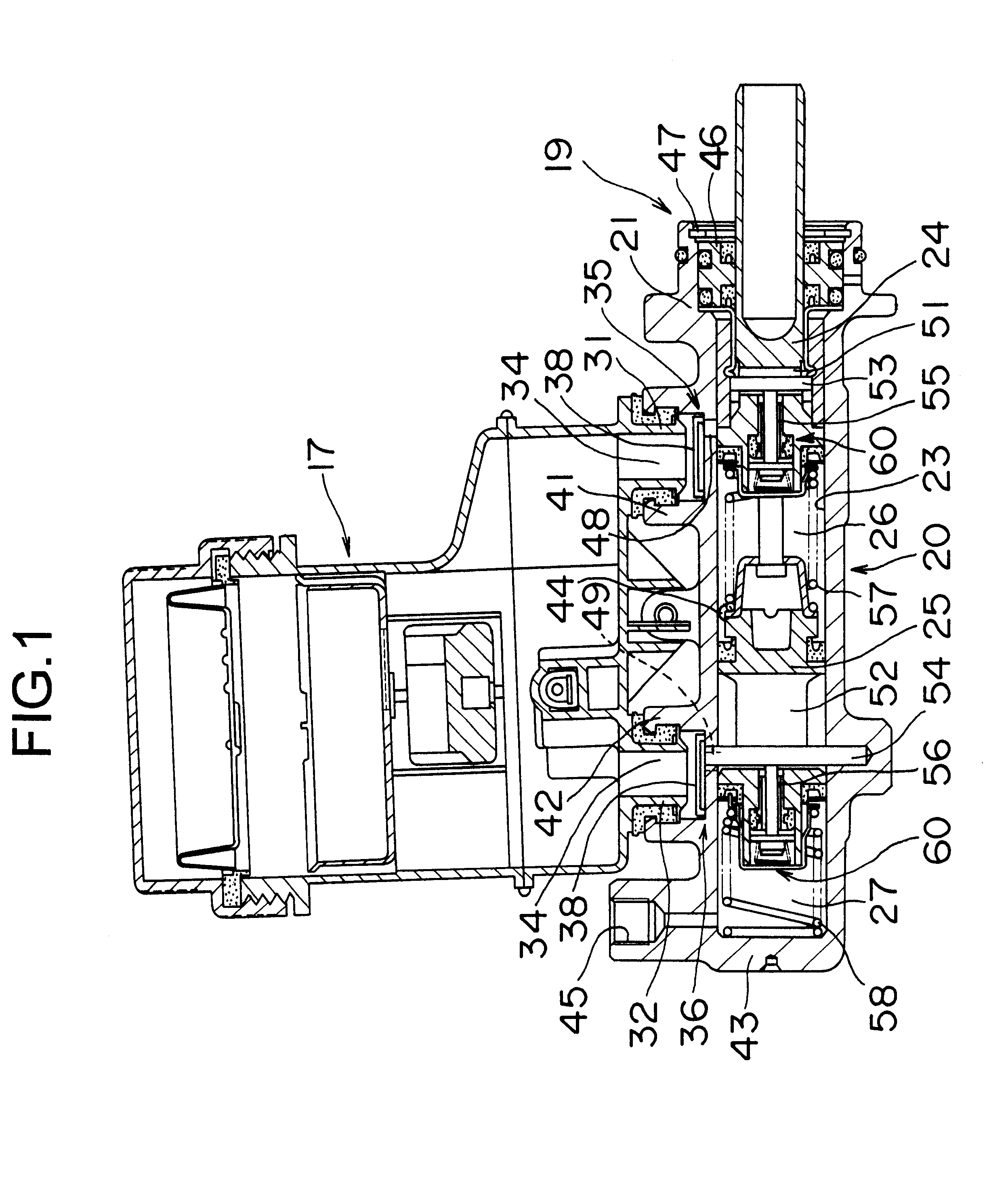
The operation of a master cylinder according to the above first embodiment of the present invention will be described by mainly referring to the primary side, and the description will be omitted as for the secondary side where the operation is similar to this. In the unoperating state shown in FIG. 1, in the piston 24, the leftmost inside surface of the slit 51 and the rear end of the rod 62 are brought into contact with the pin 53, and the center valve 60 and the throttle valve mechanism 35 are in the opening state. When the piston 24 operates and advances to the left from this state, the valve seat member 61 also advances together with the piston 24, and the center valve 60 is closed. When the piston 24 further advances, the pressure in the pressure generating chamber 26 rises, and the hydraulic fluid is sent out of the output port 44. In the above operation, during the time from the opening to the closing of the center valve 60, the hydraulic fluid in the pressure generating cham...

second embodiment

FIG. 16 is a vertical cross sectional view showing a master cylinder according to the present invention. The cylinder body 20 of this master cylinder 19 comprises a cylinder main body 21 and a cap 22 assembled thereto, and the cylinder main body 21 has two connection receiving portions 41, 42, and in the peripheral wall of the cap 22, a slant connecting hole 22a is pierced. In the cylinder main body 21, a piston guide 73 and a sleeve 74 with a flange are fixedly fitted, and in the cap 22, a sleeve 75 is fixedly fitted.

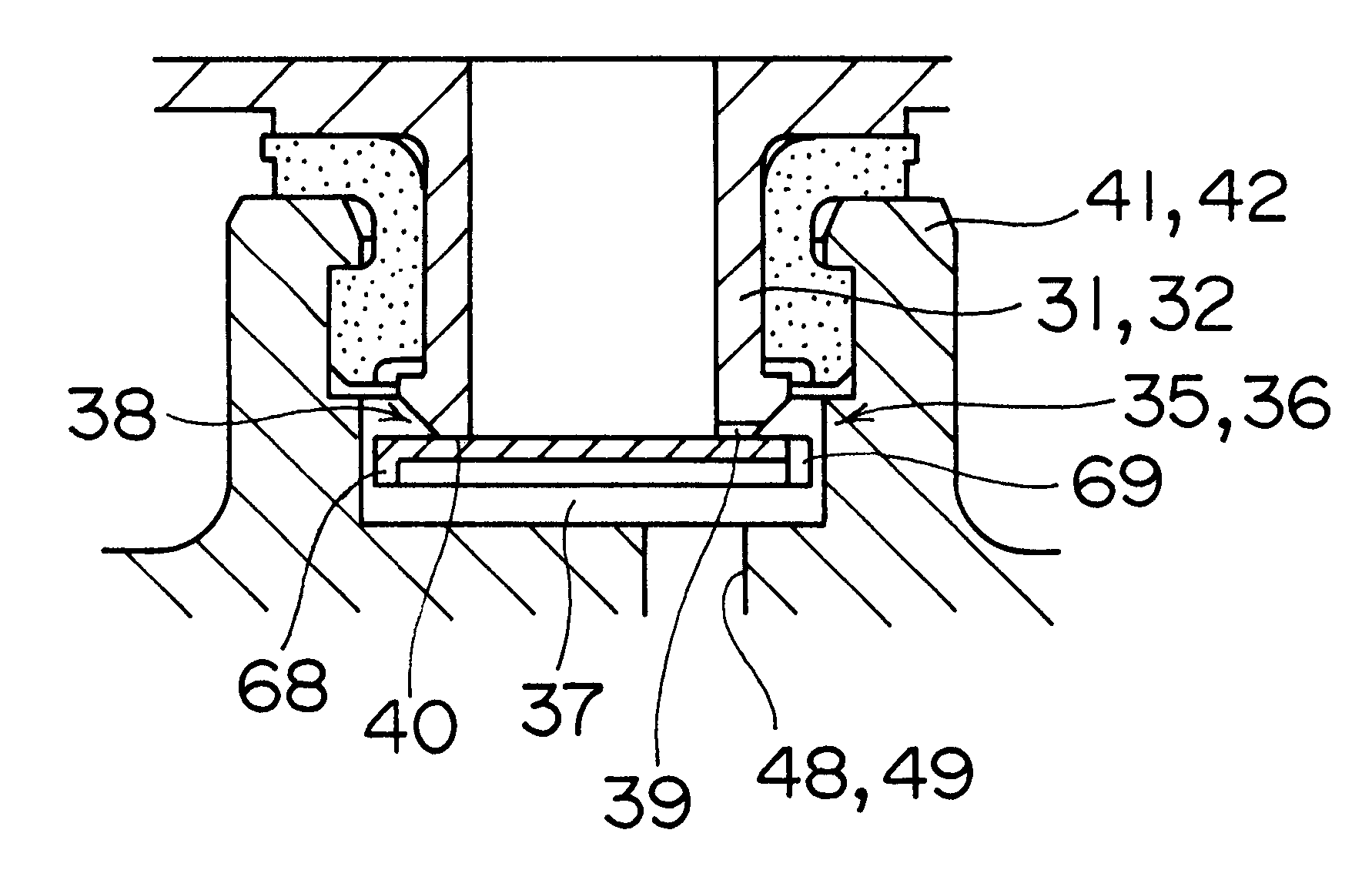
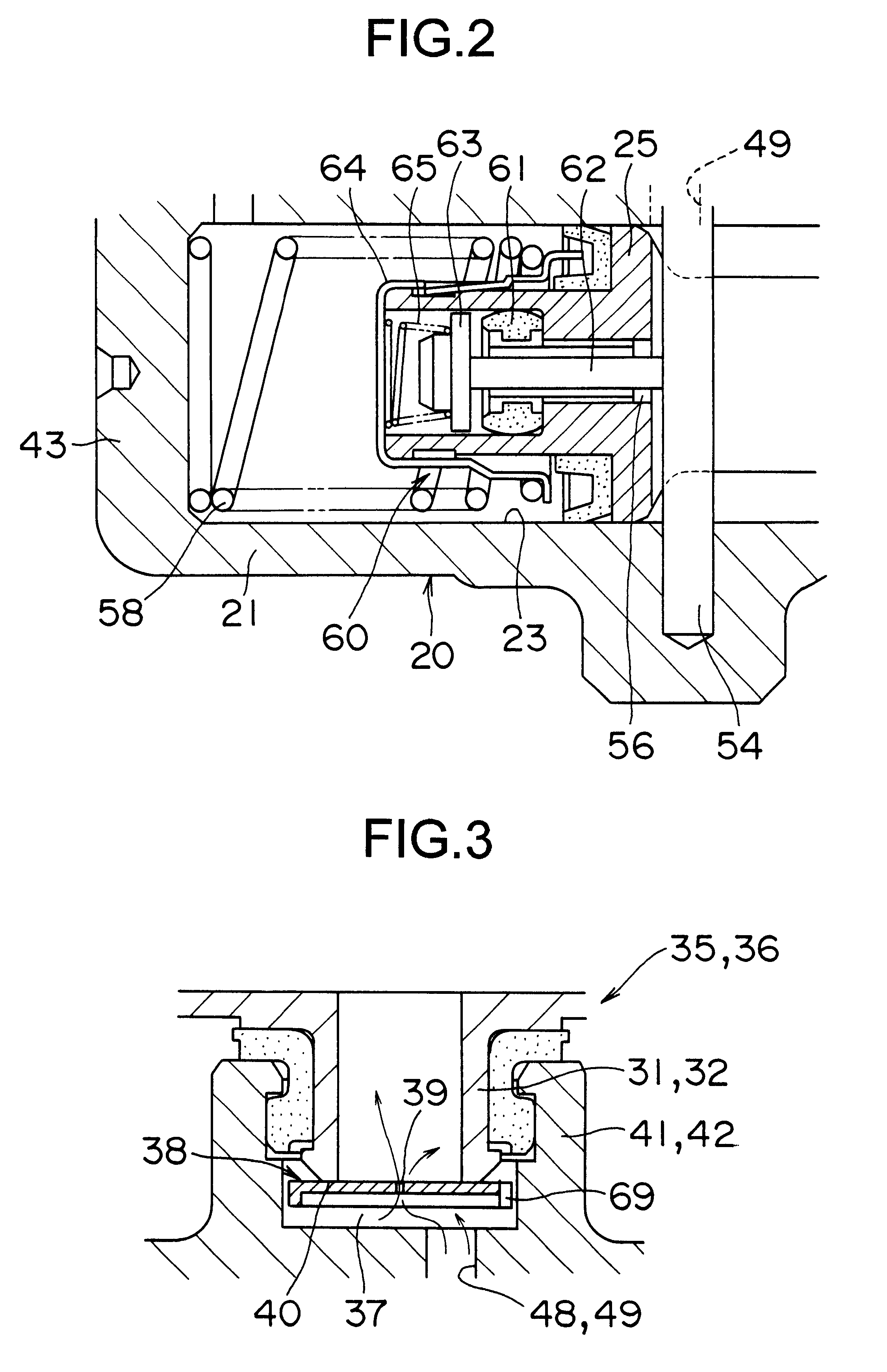
In this master cylinder 19, a primary piston 24 is freely slidably fitted in the sleeve 75 and a secondary piston 25 is freely slidably fitted in the piston guide 73 and the sleeve 74 with a flange, and by both these pistons 24, 25, a primary pressure generating chamber 26 and a secondary pressure generating chamber 27 are formed. The throttle valve mechanism 36 in this case has a floating valve body 38 with no throttle passage, and a throttle passage 39 shaped like a ...

third embodiment

FIG. 17 is a vertical cross sectional view showing a master cylinder according to the present invention, and the same reference numerals are given to the same parts as in FIG. 16. In this master cylinder 19, a circular piston guide 73 and a seal member 80 are arranged around the periphery of the secondary piston 25, and between the piston guide 73 and the seal member 80, a retainer member 81 is provided.

Furthermore, the master cylinder 19 is constituted such that a circular chamber 82 which can communicate with the reservoir 17 is provided outside the secondary piston 25 and between the piston guide 73 and the seal member 80, and in the circular chamber 82 and around the periphery of the secondary piston 25, a circular floating valve body 83 which is fluid-tightly slidable and has a throttle passage 39 is arranged inside the retainer member 81 and a seat member 84 is fixed inside the retainer member 81.

The operation of a master cylinder according to the above third embodiment will b...


PUM


Abstract

The object of the present invention is to exhibit the function of a throttle valve mechanism without making the whole of a master cylinder large-sized and to simplify the structure and to reduce the number of pieces of parts. In order to attain this object, the present invention has throttle valve mechanisms with a floating valve body which sits and throttles the flow of the hydraulic fluid to the reservoir from the pressure generating chambers when the pistons operate and which opens when the pistons do not operate, and the throttle valve mechanisms are arranged in the fluid passage for the supplementation of the hydraulic fluid, and the throttle valve mechanisms have a floating valve body with a throttle passage and a valve seat with and from which the floating valve body is brought into contact and is separated, and the valve seat is provided at the tip of the connecting portions to the cylinder body of the reservoir.

Description

FIELD OF THE INVENTION AND RELATED ART STATEMENTThe present invention relates to a master cylinder, which is suitable for use in a clutch operating unit, a brake operating unit, or the like.FIG. 26 is a cross sectional view showing one example of a master cylinder related to the present invention, which is disclosed in Japanese Patent Provisional Publication No. 10-53120. This master cylinder 1 has a piston 3 which is freely slidably fitted in a cylinder hole 2a formed in a cylinder body 2, and by the piston 3 and the cylinder body 2, a pressure generating chamber 4 and a hydraulic fluid waiting chamber 5 are sectioned. To the piston 3, a valve mechanism 6 and a throttle valve mechanism 7 are attached on the extension of the axis. In the valve mechanism 6, a flange 10 integrated with a rod 9 is separated from a circular member 11 to open an axial hole 12 as the piston 3 retreats to the restoration position by a return spring 8 provided in the pressure generating chamber 4, and the f...

Claims


Application Information

Patent Timeline
Patent Type & Authority Patents(United States)
IPC IPC(8): B60T11/26B60T11/10B60T11/28B60T11/16B60T11/20
CPCB60T11/20B60T11/26B60T11/28
Inventor CHIBA, SHUSAKUSUGIMOTO, RIICHIROU
Owner DIESEL KIKI CO LTD
Why Eureka
Try Eureka