An Array-Based Passive Detection Method for Weak Line Spectrum Targets
A detection method and weak line spectrum technology, applied in the field of passive detection of weak line spectrum targets, can solve the problems of long operation time, weak target detection failure, inability to perform multi-target resolution of the same frequency line spectrum, etc., and achieve good resistance to strong broadband coherence. Effects of interference, good weak line spectrum target detection ability
- Summary
- Abstract
- Description
- Claims
- Application Information
AI Technical Summary
Problems solved by technology
Method used
Image
Examples
specific Embodiment approach 1
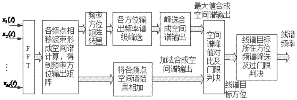
[0044] Specific implementation mode one: combine figure 1 and image 3 An array-based passive detection method for weak line spectrum targets in this embodiment is described, which is specifically prepared according to the following steps:
[0045] Step 1. Signal x received by M array elements 1 (t),x 2 (t),...,x M (t) Perform fast Fourier transform (FFT: Fast Fourier transform) respectively to obtain the spectrum X of the signal received by each array element 1 (f),X 2 (f)…X M (f); then each array element at the frequency point f i The spectral value of can be expressed as X 1 (f i ),X 2 (f i )…X M (f i );
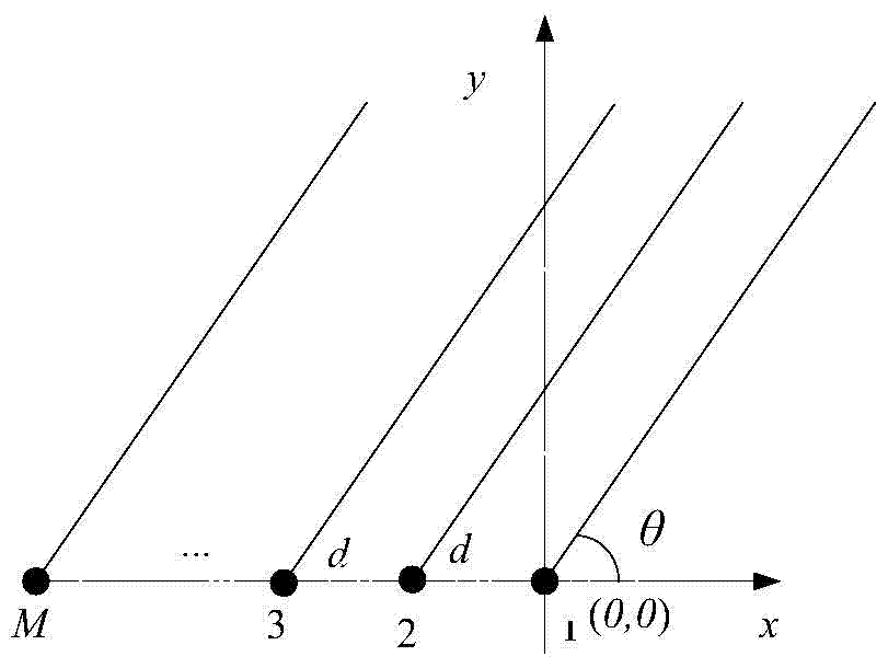
[0046] Among them, M is the number of array elements, f is the frequency, f i Indicates the i-th frequency point within the signal processing frequency band, the value range of i is 1~L, f 1 is the lower limit of signal processing frequency point, f L is the upper limit of the signal processing frequency, the superscript T means transpose; L=B / Δf, B is th...
specific Embodiment approach 2
[0068] Specific embodiment 2: The difference between this embodiment and specific embodiment 1 is that in step 2, the frequency-domain beamforming processing calculation formula adopts CBF (conventional beamforming) or MVDR (minimum variance distortion-free response beamforming) processing, and the beamforming is required to be robust CBF is used when the performance is the best, and MVDR beamforming is used when good azimuth resolution is required. Other steps and parameters are the same as those in Embodiment 1.
specific Embodiment approach 3
[0069] Specific embodiment three: the difference between this embodiment and specific embodiment one or two is: the frequency orientation output matrix P after the transposition in step three T Specifically:
[0070]
[0071] where the frequency f is given by [f 1 ,f 2 ,... f L ] consists of a total of L frequency points. Other steps and parameters are the same as those in Embodiment 1 or Embodiment 2.
PUM
 Abstract
Description
Claims
Application Information
 - R&D
- Intellectual Property
- Life Sciences
- Materials
- Tech Scout
- Unparalleled Data Quality
- Higher Quality Content
- 60% Fewer Hallucinations
Browse by: Latest US Patents, China's latest patents, Technical Efficacy Thesaurus, Application Domain, Technology Topic, Popular Technical Reports.
© 2025 PatSnap. All rights reserved.Legal|Privacy policy|Modern Slavery Act Transparency Statement|Sitemap|About US| Contact US: help@patsnap.com


