
A system for imaging astronomical objects

A target imaging and astronomical technology, applied in telescopes, optics, instruments, etc., can solve the problems of blurred local areas of the image, low probability of the entire clear image appearing, inappropriate evaluation of image quality, etc., to achieve high definition and improve luck The effect of the probability of the image

Active Publication Date: 2017-07-28
NAT UNIV OF DEFENSE TECH
View PDF13 Cites 0 Cited by
  • Summary
  • Abstract
  • Description
  • Claims
  • Application Information

AI Technical Summary

Problems solved by technology

However, the image quality is related to the intensity of atmospheric turbulence. The index of energy concentration of a point target cannot accurately describe the intensity of atmospheric turbulence, so it is not suitable for evaluating image quality.
The gray gradient evaluation method evaluates the imaging quality by calculating the contrast of the target contour in the image. When this method is applied to an extended astronomical target, because the image contains many halo regions, the imaging quality of each halo region changes independently, which will lead to The probability of the entire clear image appearing is very low, so that the selected image has serious blurring problems in local areas
[0004] The mechanism of atmospheric turbulence is complex, and the light field emitted by the target will be randomly disturbed
Traditional imaging methods obtain imaging results by superimposing target disturbance light fields. This process does not use atmospheric disturbance information, and the real light field distribution cannot be reconstructed from the image.
Therefore, without using guide stars to assist imaging, it is difficult to judge directly from the target image whether its imaging is disturbed by the atmosphere, or the degree of interference

Method used


Image

  • A system for imaging astronomical objects
  • A system for imaging astronomical objects
  • A system for imaging astronomical objects

Examples


Embodiment Construction

[0049] The present invention will be described in further detail below in conjunction with the accompanying drawings.

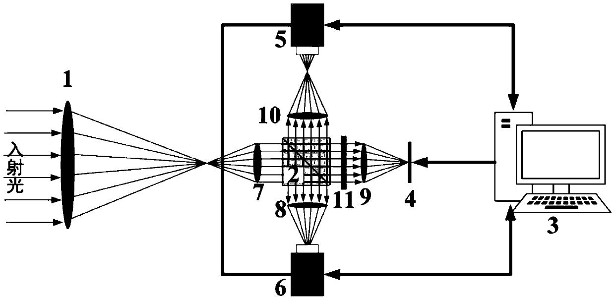
[0050] figure 1 Among them, the focal ratios of the relay mirrors 7, 8, 9, and 10 with the same focal length should be greater than the focal ratio of the telescope objective lens 1. The light band of the wide-spectrum polarization beam splitter 2 can be selected according to the target radiation characteristics (such as visible light band or infrared band). The size of the wide-spectrum polarization beam-splitter prism 2 should meet the requirement that all the light emitted by the relay lens 1 can enter, and the relay mirrors 7, 8, 9, and 10 should be installed as close as possible to the wide-spectrum polarization beam-splitter prism 2 to reduce the imaging loss. Vignetting effect. In the figure, the in-focus camera 6 and the out-of-focus camera 5 send image data to the central control device 3 . The central control device 3 sends image acquisition cont...


PUM


Abstract

The invention provides an astronomical object imaging system. According to the technical scheme of the invention, the system comprises a telescope objective lens, a wide-spectrum polarization splitting prism, a central control device, a digital miniature reflector type spatial light modulator, a first camera, a second camera, a first relay lens, a second relay lens, a third relay lens, a fourth relay lens, and a wide-spectrum quarter-wave plate. The first relay lens is located between the telescope objective lens and the wide-spectrum polarization splitting prism. The second relay lens is located between the wide-spectrum polarization splitting prism and the second camera. The third relay lens is located between the wide-spectrum polarization splitting prism and the digital miniature reflector type spatial light modulator. The fourth relay lens is located between the wide-spectrum polarization splitting prism and the first camera. The wide-spectrum quarter-wave plate is located between the wide-spectrum polarization splitting prism and the third relay lens. The first, second, third and fourth relay lens are respectively opposite to four usable surfaces of the wide-spectrum polarization splitting prism for placement. The system can achieve the clear imaging of a big-view-field astronomical object.

Description

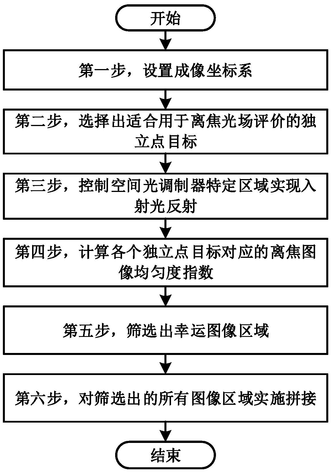
technical field [0001] The invention belongs to the technical field of astronomical target imaging, relates to a method and system for clear imaging of astronomical targets, and further relates to a method and system for realizing clear imaging of astronomical targets by evaluating the defocused image quality of point targets. Background technique [0002] At present, there are three main methods for imaging astronomical targets, namely adaptive optics method, image deconvolution method and lucky imaging method. Adaptive optics methods are expensive and only work with small fields of view. Image deconvolution methods are time-consuming and have limited improvement in image quality. The method of lucky imaging obtains clear imaging of astronomical targets by taking long-time shots of the target, selecting those with excellent imaging from the image sequence and superimposing them. This method is simple to implement and low in cost, and has been widely used. [0003] In orde...

Claims


Application Information

Patent Timeline
Patent Type & Authority Patents(China)
IPC IPC(8): G02B23/12
CPCG02B23/12
Inventor 张文静张煊喆刘泽金曹毓宁禹
Owner NAT UNIV OF DEFENSE TECH
Learn More