
Combination structure of nuclear power plant reactor pressure vessel and shielding wall

A technology for reactors and pressure vessels in nuclear power plants, applied in the fields of reactors, nuclear power generation, nuclear engineering, etc., can solve the problem of inability to provide a return flow channel for external cooling, and achieve the effect of rapid and continuous cooling

Active Publication Date: 2018-04-27
中广核工程有限公司 +1
View PDF5 Cites 0 Cited by
  • Summary
  • Abstract
  • Description
  • Claims
  • Application Information

AI Technical Summary

Problems solved by technology

[0005] In some published nuclear power designs, the special structural design of the support ring of the reactor pressure vessel provides a natural circulation return flow channel for external cooling. High, unable to provide return flow path for out-of-heap cooling

Method used


Image

  • Combination structure of nuclear power plant reactor pressure vessel and shielding wall

Examples


Embodiment Construction

[0022] In order to make the object, technical solution and beneficial technical effects of the present invention clearer, the present invention will be further described in detail below in conjunction with the accompanying drawings and specific embodiments. It should be understood that the specific implementations described in this specification are only for explaining the present invention, not for limiting the present invention.

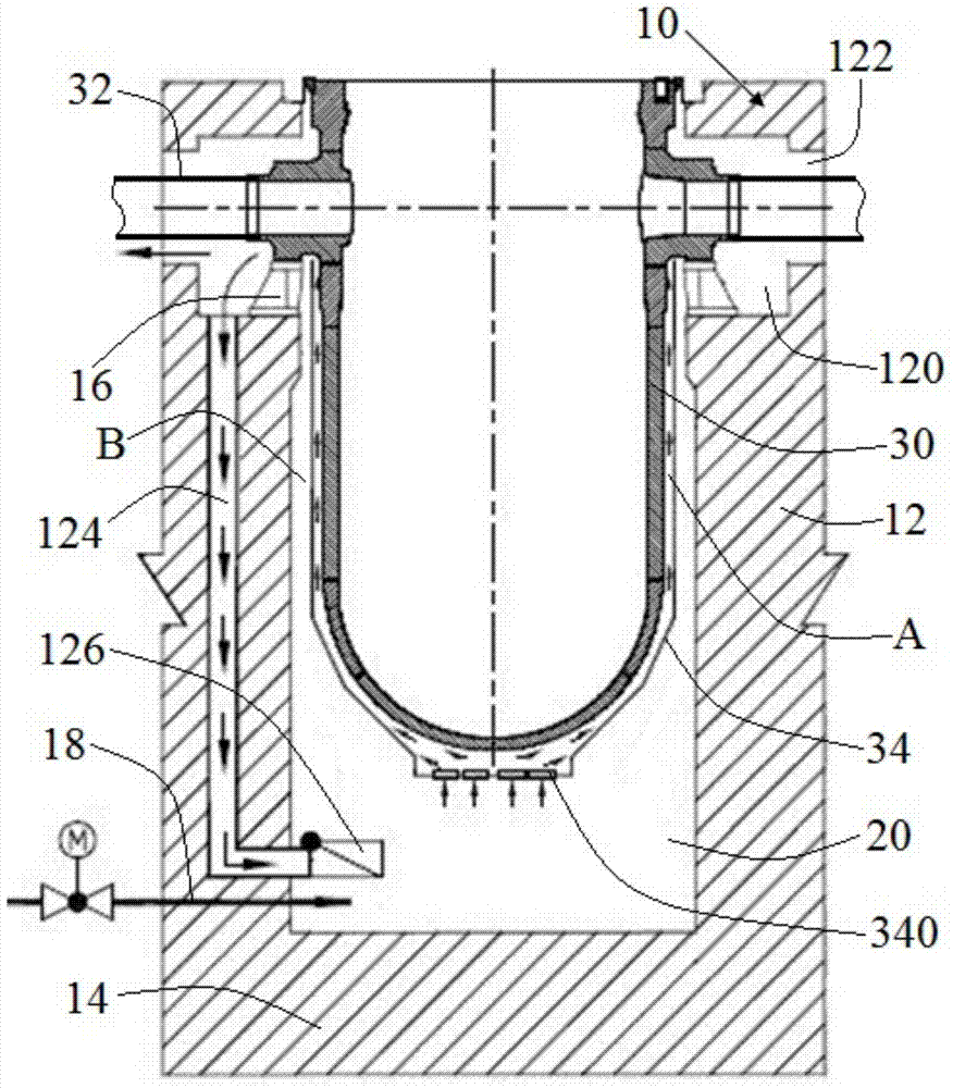
[0023] see figure 1 The combined structure of the nuclear power plant reactor pressure vessel and shielding wall of the present invention includes a pit shielding wall 10 , a pit 20 surrounded by the pit shielding wall 10 and a reactor pressure vessel 30 arranged in the pit 20 . The upper part of the reactor pressure vessel 30 is connected with a plurality of main pipes 32 passing through the shielding wall 10 of the reactor pit.

[0024] The pit shielding wall 10 includes a side wall 12 and a bottom plate 14 . The side wall 12 is provided with a...


PUM


Abstract

A composite nuclear reactor pressure vessel and barrier shield comprising: a barrier shield being formed with a water injection pipe connected to a reactor pit lower portion, wherein the reactor pit is enclosed by the barrier shield; this aims to maintain the melt in the reactor pressure vessel. The reactor pressure vessel having thermal insulation is seated in the reactor pit with a passageway between the insulation and the reactor pressure vessel and between the insulation and the barrier shield. The barrier shield defining a receiving chamber at an upper inner wall and having a reflux flow channel, which connects the receiving chamber with the bottom of the reactor pit. The reflux flow channel may define a bottom outlet in the reactor pit with a blocking element for use in normal operation, but which can be opened under severe accident conditions. The passageway between the insulation and the barrier shield may be a normal ventilation channel. The barrier shield may be characterised in that the annular receiving chamber is located at a height indicating position where the coolant lines are connected to the reactor.

Description

technical field [0001] The invention belongs to the field of dealing with severe accidents of nuclear power plants, and more specifically relates to a combined structure of reactor pressure vessels and shielding walls of nuclear power plants capable of handling severe accident conditions. Background technique [0002] Since the Chernobyl, Three Mile Island, and Fukushima nuclear power plant accidents, countries all over the world have paid unprecedented attention to nuclear power safety. While putting forward higher requirements for the probability of serious accidents in next-generation nuclear power plants, they have combined countries' Based on the characteristics of nuclear power units in service and under construction, an improvement plan for severe accident mitigation strategies is proposed. In the new version of the "Nuclear Power Plant Design Safety Regulations" (HAF102) and the IAEA guideline NS-G-1.10 issued by the China Nuclear Safety Administration on April 18, 2...

Claims


Application Information

Patent Timeline
Patent Type & Authority Patents(China)
IPC IPC(8): G21C15/18
CPCG21C9/016G21C13/024G21C15/18Y02E30/30G21C9/004G21C13/10
Inventor 周媛霞王庆礼程浩彭国胜刘永曹涛陈兴许晨德黄威
Owner 中广核工程有限公司
Learn More