
Apparatus for acting on material to be conveyed in a material conveying system

A technology for conveying channels and materials, applied to conveyors, conveying bulk materials, applications, etc., can solve the problems of blocking supplementary air, blocking the entry of flow medium, and hindering the movement of materials to achieve effective volume and improve conveying efficiency.

Inactive Publication Date: 2016-04-13
MARICAP OY
View PDF10 Cites 0 Cited by
  • Summary
  • Abstract
  • Description
  • Claims
  • Application Information

AI Technical Summary

Problems solved by technology

One drawback of the prior art in particular is that the material being conveyed may block the entry of the flowing medium and more specifically the entry of make-up air in the vicinity of the blocking means
This prevents the material from starting to move when the blocking device leaves the channel space in the material conveying channel of the pneumatic tube material conveying system

Method used


Image

  • Apparatus for acting on material to be conveyed in a material conveying system
  • Apparatus for acting on material to be conveyed in a material conveying system
  • Apparatus for acting on material to be conveyed in a material conveying system

Examples


Embodiment Construction

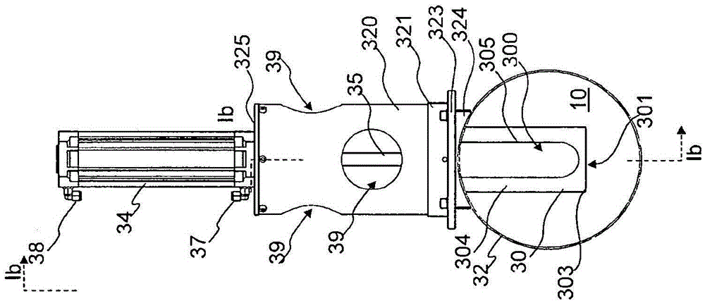
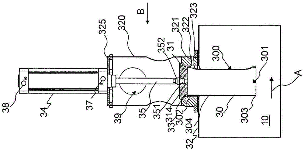
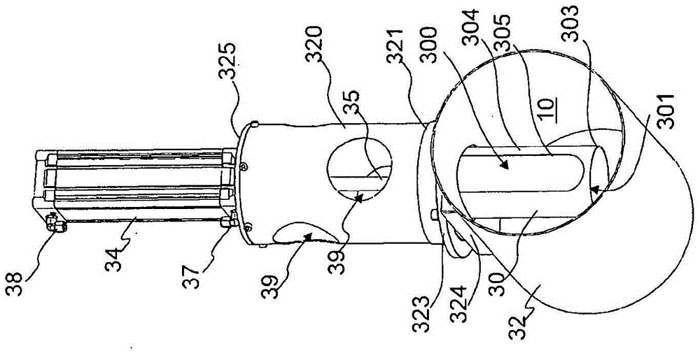
[0018] Figure 1a-1c , 2a-2c and 3a-3c show an apparatus according to one embodiment of the invention. The device is adapted to act on the material to be conveyed in the material conveying channel. The device comprises blocking means 30 which can be arranged in the material conveying channel. The blocking device 30 is movable between at least two positions (a first position and a second position), in the first position, the blocking device 30 extends into the channel space 10 of the material conveying channel, and in the second position, the blocking device Essentially no extension into the channel space of the material conveying channel. The drive means 34, 35 are arranged to move the blocking means. In the embodiment of the accompanying drawings, the blocking means 30 is a member extending into the material conveying channel, into the channel space 10 of the channel part, when the material abuts against the blocking means 30 in the material conveying channel, for example ...


PUM


Abstract

Apparatus for acting on material to be conveyed in a material conveying channel, which apparatus comprises an impeding means (30), which can be arranged in the material conveying channel, which impeding means (30) can be moved between at least two positions, a first position, in which the impeding means (30) extends into the channel space (10) of the material conveying channel, and a second position, in which the impeding means does not essentially extend into the channel space of the material conveying channel. Means (31, 33) are arranged in connection with the impeding means (30), for conducting flowing medium, such as replacement air, from outside the material conveying channel into the channel space (10) of the material conveying channel to the point of, or into the vicinity of, the impeding means (30).

Description

technical field [0001] The object of the invention is a device as defined in the preamble of claim 1 . [0002] The invention also relates to a system according to claim 18 . Background technique [0003] The present invention relates generally to material conveying systems, such as pneumatic partial vacuum conveying systems, and more particularly to waste collection and conveyance, such as household waste conveyance. These systems are mentioned inter alia in publications WO2009 / 080880, WO2009 / 080881, WO2009 / 080882, WO2009 / 080883, WO2009 / 080884, WO2009 / 080885, WO2009 / 080886, WO2009 / 080887 and WO2009 / 080888. The invention also relates to waste supply means, such as input points or waste chutes, with which waste is conveyed, usually by gravity, for example from an upper input hole of a residential building to a lower collection space or corresponding container. [0004] Systems that rely on differential pressure or suction to transport waste in pipes are known in the art. I...

Claims


Application Information

Patent Timeline
Patent Type & Authority Applications(China)
IPC IPC(8): B65F5/00B65G53/04B65G53/46E04F17/12
CPCE04F17/12B65F5/005B65G53/04B65G53/46E04F17/10B65G53/24B65G53/58B65G2205/04
Inventor G·桑德霍姆
Owner MARICAP OY
Learn More