Image formation apparatus and developer supply method

A developer and image technology, applied in the electrical recording process using charge graphics, equipment and instruments using the electrical recording process using charge graphics, etc., can solve the problems of image generation of speckle patterns or stripe patterns, image quality degradation, etc., to achieve Effects of reducing installation time, preventing image quality degradation, and suppressing deviation

Inactive Publication Date: 2016-01-27
KYOCERA DOCUMENT SOLUTIONS INC
View PDF8 Cites 0 Cited by
  • Summary
  • Abstract
  • Description
  • Claims
  • Application Information

AI Technical Summary

Problems solved by technology

This variation in layer thickness (layer thickness unevenness) causes a speckle pattern or a stripe pattern, etc., in the image on the paper on which the image is formed, resulting in a decrease in image quality.

Method used


Image

  • Image formation apparatus and developer supply method
  • Image formation apparatus and developer supply method
  • Image formation apparatus and developer supply method

Examples


no. 1 approach

[0028] First, a first embodiment of the present invention will be described.

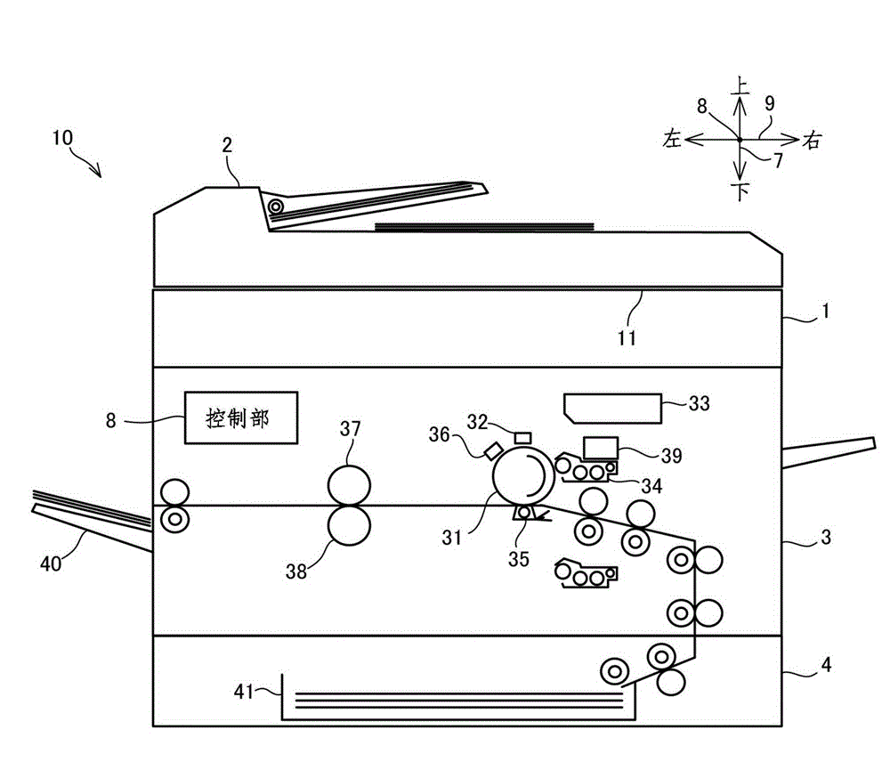
[0029]figure 1 The image forming apparatus 10 according to the first embodiment of the present invention is shown in . like figure 1 As shown, the image forming apparatus 10 includes: an image reading unit 1, an image forming unit 3, a paper feeding unit 4, a control unit 8, and a first motor 86 (refer to Figure 4 ) and the second motor 87 (refer to Figure 4 )Wait. Among them, the control unit 8 is an example of the drive control unit of the present invention. The first motor 86 is an example of the first driving unit in the present invention. The second motor 87 is an example of the second driving unit in the present invention. In addition, the image forming apparatus 10 is only an example of the image forming apparatus of the present invention, and the image forming apparatus of the present invention may also be a printer, a facsimile machine, a copier, or a digital multifunction machine ha...

no. 2 approach

[0074] Below, refer to Figure 6 to Figure 8 , the second embodiment of the present invention will be described. In addition, the same structure as the structure of the said 1st Embodiment is assigned the code|symbol used in 1st Embodiment, and the description of the structure is abbreviate|omitted. The second embodiment differs from the first embodiment in that a new Image 6 Step S11 and step S12 are two processes.

[0075] Below, refer to Image 6 The flow chart of FIG. 2 illustrates another example of the driving control of the first motor 86 and the second motor 87 at the time of the toner installation. In the following description, the toner container 39 for initial replenishment is attached to the image forming apparatus 10 in the state where the cartridge main body 60 is empty, and thereafter is performed as an initial preparation operation of the image forming apparatus 10. The toner is installed.

[0076] If it is determined in step S1 that the toner container 3...

no. 3 approach

[0088] Below, refer to Figure 10 , the third embodiment of the present invention will be described. In addition, the reference numerals used in the first embodiment are assigned to the same configurations as those of the above-mentioned first embodiment, and descriptions of the configurations are omitted. In addition, in the third embodiment and the fourth embodiment to be described later, the second motor 87 is an example of the driving unit of the present invention.

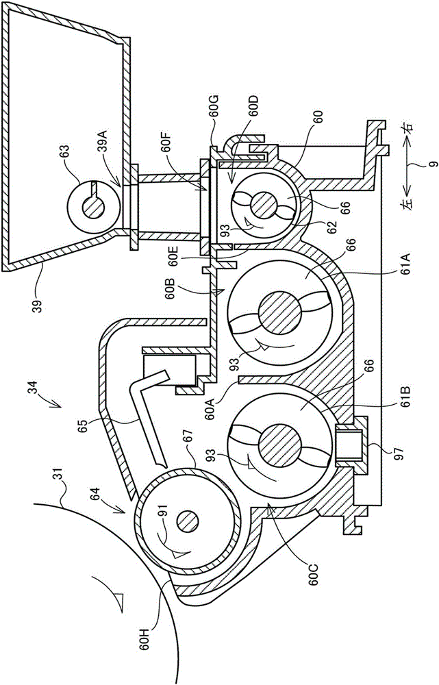
[0089] In the configuration of the image forming apparatus 10 according to the first embodiment described above, when the developing roller 64 comes into contact with the developer and rotates, the developer is charged by the friction at the time of the contact. In addition, when the developer layer held on the developing roller 64 passes through the front end of the regulating blade 65 , the developer is further charged by friction with the developing roller 64 and the regulating blade 65 . In particular, w...


PUM


Abstract

An image formation apparatus (10) according to the present invention is provided with a development apparatus (34). A first accommodation chamber (60B) and second accommodation chamber (60C) are formed in a case main body (60) of the development apparatus (34). The first accommodation chamber is provided with a first stirring screw (61A) and the second accommodation chamber is provided with a second stirring screw (61B). The second accommodation chamber is provided with a development roller (64). A control unit (8) controls the driving of a first motor (86) and a second motor (87). During toner installation, the control unit (8) controls the driving of the first motor (86), in a state in which the second motor (87) is stopped, such that the rotation speed of the first motor (86) is higher than the rotation speed during a development operation. If specific conditions are satisfied, the control unit (8) starts controlling the driving of the second motor (87) and the second motor (87) is driven so as to rotate.

Description

technical field [0001] The present invention relates to an image forming apparatus having a developing device and a developer supply method for supplying developer to the inside of the developing device. Background technique [0002] A developing device is incorporated in an image forming apparatus such as a copier or a printer that forms an image on paper by electrophotography. A storage chamber for storing developer such as toner is formed inside the developing device. A developing roller, a conveying member for conveying developer to the developing roller, and the like are provided in the storage chamber. The developing roller and the conveyance member are driven by a driving force of a motor or the like. When the developer is accommodated in the storage chamber, the conveying member conveys the developer toward the developing roller, and holds the developer on the surface of the developing roller by contacting and rotating the conveyed developer. [0003] In recent ye...

Claims


Application Information

Patent Timeline
Patent Type & Authority Applications(China)
IPC IPC(8): G03G15/08G03G21/00
CPCG03G15/0893G03G15/0887
Inventor 仓增浩二山口晃史
Owner KYOCERA DOCUMENT SOLUTIONS INC
Why Eureka
Try Eureka