

Tubular metal body and electrophotographic photoreceptor
Active Publication Date: 2020-10-01
FUJIFILM BUSINESS INNOVATION CORP
View PDF0 Cites 0 Cited by
- Summary
- Abstract
- Description
- Claims
- Application Information
AI Technical Summary
Benefits of technology
The patent text describes an impact-pressed tubular metal body that has a reduced generation of a shock line and thickness deviation compared to conventional tubular metal bodies. This is achieved by controlling the ratio of surface roughness of the outer peripheral surface of the bottom part to the surface roughness of the center portion of the tubular part in the axis direction. The ratio should be between 2 and 4000, with a preferred range of 2.75 and 3800. The patent also mentions the Vickers hardness of the outer peripheral surface of the bottom part and the average crystal grain diameter of the outer peripheral surface of the bottom part. By controlling these factors, the tubular metal body has improved impact resistance and reduced surface roughness.
Problems solved by technology
However, aspects of the non-limiting embodiments are not required to address the advantages described above, and aspects of the non-limiting embodiments of the present disclosure may not address advantages described above.
Method used
View moreImage
Smart ImageViewing Examples

Examples
examples
[0294]Examples of the present disclosure will now be described in further detail, but the present disclosure is not limited by the examples. Unless otherwise noted, “parts” means “parts by mass”.
Login to View More PUM
| Property | Measurement | Unit |
|---|---|---|
| Vickers hardness HV2 | aaaaa | aaaaa |
| Vickers hardness HV2 | aaaaa | aaaaa |
| Vickers hardness HV2 | aaaaa | aaaaa |
Abstract
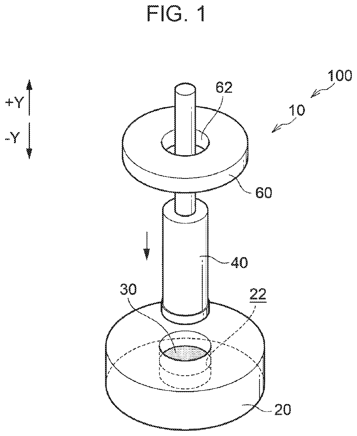
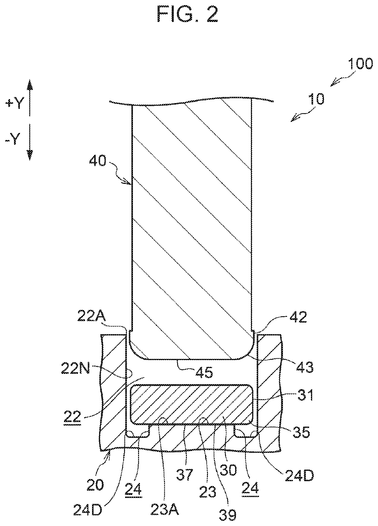
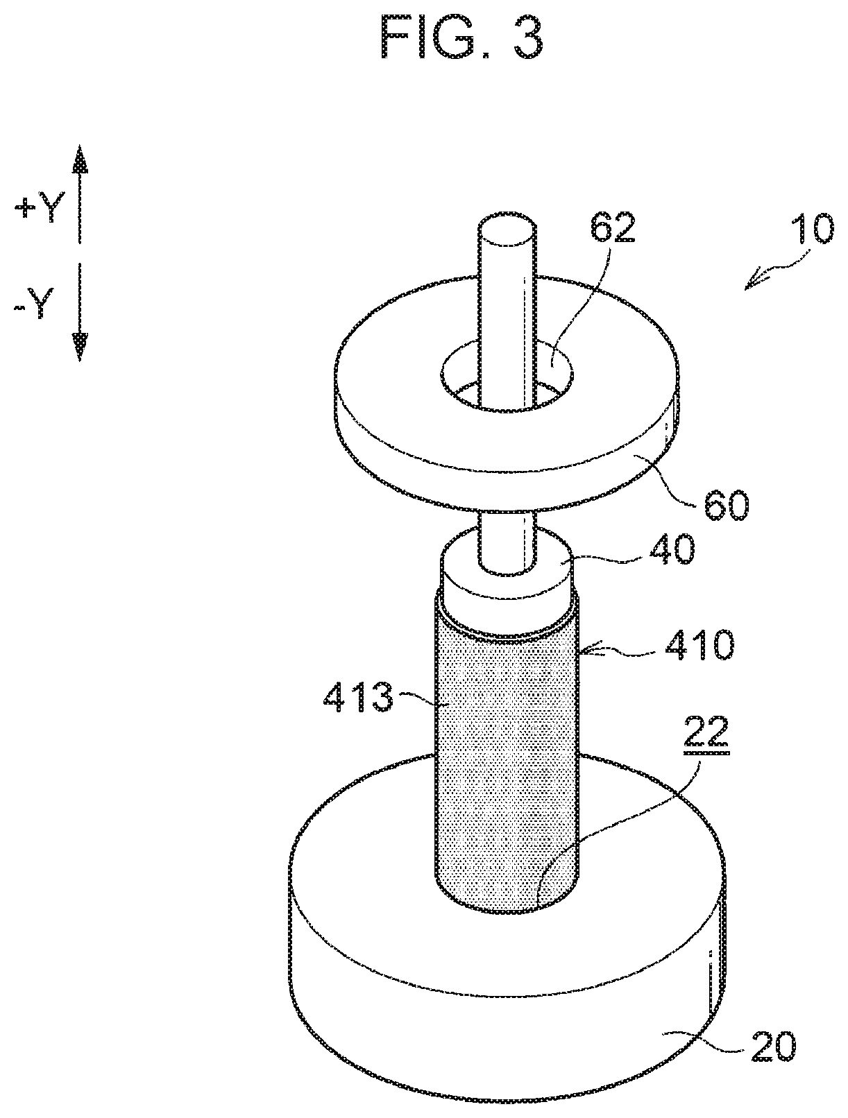
A tubular metal body includes a tubular part having an opening at one end in an axis direction; and a bottom part disposed at another end of the tubular part in the axis direction. The ratio (Rz1 / Rz2) of a surface roughness Rz1 of an outer peripheral surface of the bottom part to a surface roughness Rz2 of an outer peripheral surface of a center portion of the tubular part in the axis direction is in a range of 2 or more and 4000 or less. A Vickers hardness HV1 of the outer peripheral surface of the bottom part is 5 HV or more and 27 HV or less smaller than a Vickers hardness HV2 of the outer peripheral surface of the center portion of the tubular part in the axis direction.
Description
CROSS-REFERENCE TO RELATED APPLICATIONS[0001]This application is based on and claims priority under 35 USC 119 from Japanese Patent Application No. 2019-059408 filed Mar. 26, 2019.BACKGROUND(i) Technical Field[0002]The present disclosure relates to a tubular metal body and an electrophotographic photoreceptor using the tubular metal body.(ii) Related Art[0003]One of the methods for mass-producing tubular metal bodies such as thin-walled metal containers at low cost known heretofore is an impact press method in which a tubular metal body is formed by applying an impact to a metal blank (slag) on a female mold (cavity plate) by using a male mold (punch).[0004]For example, Japanese Unexamined Patent Application Publication No. 2008-132503 discloses “a method for manufacturing a bottomed container by loading a plastic material such as a slag into a cavity of a die and pressing the slag with a punch freely displaceable with respect to the die so as to plastically deform the plastic mater...
Claims
Login to View More Application Information
Patent Timeline
 Patent Type & AuthorityApplications(United States)
IPC IPC(8): G03G5/10G03G5/05
CPCG03G5/102G03G5/0542G03G15/75G03G5/0564G03G5/0525
InventorSHINGU, KENTAOGAWA, HIROAKIAGATSUMA, MASARUTANAKA, YASUKIYAMAUCHI, TSUBASANAKAMURA, AKIHIKO
OwnerFUJIFILM BUSINESS INNOVATION CORP