
Medical terminal warning device for intensive care unit

An alarm device, medical terminal technology, applied in nursing facilities, medical science, hospital equipment, etc., can solve the problems of negligence, missing the first time, unable to obtain the first time, etc., and achieve the effect of improving work efficiency

Inactive Publication Date: 2016-02-03
ZHENGZHOU DACHENG SOFTWARE TECH CO LTD
View PDF6 Cites 3 Cited by
  • Summary
  • Abstract
  • Description
  • Claims
  • Application Information

AI Technical Summary

Problems solved by technology

[0003] The traditional ICU has a relatively comprehensive configuration of first aid equipment. However, for the patient's turning over, massage, and implementation of new doctor's orders, etc., the nursing staff still needs to perform manual execution in a timely manner.
Since most of the patients in the ICU are highly critical patients, it is very common to be unable to speak or turn on their own. For the nursing staff who care for multiple patients in the same ICU, it is important to remember that each care recipient needs to be cared for. The specific time and nursing items are very difficult, usually rely on the memory of the nursing staff or the alarm mode of the nursing PC software application interface; such traditional ICU nursing situation, it is easy to cause the nursing staff to be too busy and neglect In other cases, forgetting that the specific care recipient in the specific ICU misses the best care time for the care recipient, especially the temporary medical order issued by the doctor for the specific ICU patient cannot be obtained in the first time, thus missing the first time for the best care, and Unable to cooperate with doctors to provide timely treatment for the care recipients

Method used


Image

  • Medical terminal warning device for intensive care unit

Examples


Embodiment Construction

[0016] Below in conjunction with accompanying drawing, the present invention will be further described:

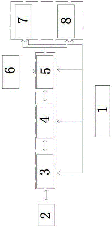
[0017] The medical terminal alarm device in the intensive care unit includes a host computer 2, a power supply module 1 that provides power for the alarm device, a logic control module connected to the host computer 2 through a communication module, and an input module 6 connected to the logic control module, The logic control module is arranged in the ICU ward, and the logic control module is connected and controlled with an alarm device arranged in the ICU ward; the alarm device includes a voice that is arranged at a conspicuous position near a specific ICU patient bed. Warning device 7 and light warning device 8;

[0018] The voice warning device 7 and the light warning device 8 are arranged in parallel;

[0019] The light warning device 8 includes a plurality of indicator lights with different colors; each indicator light is arranged in parallel; The connected logic ...


PUM


Abstract

The invention discloses a medical terminal warning device for an intensive care unit. The device comprises an upper computer, a power supply module for providing power to a warning device, a logic control module which is connected with the upper computer by virtue of a communication module and an input module connected with the logic control module, wherein the logic control module is arranged in the ICU, and is connected with and used for controlling the warning device which is arranged in the ICU; and the warning device comprises a voice warning device and a flash warning device which are arranged at conspicuous positions close to the specific sickbed of an ICU patient. According to the device, the warning indicating lamp and the voice warning device are arranged at conspicuous positions close to the sickbed of each patient in the ICU, changes of patient conditions can be fed back in time, specific nursing staff is warned to carry out preset medical order executive warning nursing for the specific ICU patient in time, and the nursing staff is warned to check temporarily added medical orders and the like in time, so that emergent disposed measure can be carried out by the nursing staff in first time, the working efficiency of the nursing staff can be improved, and a great warning effect for providing medical nursing work for ICU patients in first time can be achieved.

Description

technical field [0001] The invention relates to nursing auxiliary equipment for ICU, in particular to a medical terminal alarm device for intensive care unit. Background technique [0002] Intensive Care Unit, also known as ICU (abbreviation for IntensiveCareUnit). Intensive medical care is a form of medical organization management that integrates modern medical care technology with the development of medical care profession, the birth of new medical equipment and the improvement of hospital management system. The ICU gathers critically ill patients and provides the best guarantee in terms of manpower, material resources and technology, in order to obtain a good treatment effect. The ICU has a central monitoring station to directly observe all the monitoring beds. Each bed occupies a wide area, and the beds are separated by glass or curtains. ICU equipment must be equipped with bedside monitors, central monitors, multifunctional respiratory therapy machines, anesthesia ma...

Claims


Application Information

Patent Timeline
IPC IPC(8): A61B5/00A61G12/00
Inventor 曹建凯董丽莎许媛王小伟姜波李予封陈贺明
Owner ZHENGZHOU DACHENG SOFTWARE TECH CO LTD
Learn More