Ophthalmic Silicone Oil Removal Device

A technology for removing device and silicone oil, applied in ophthalmic surgery and other directions, can solve the problems of increasing patient pain, surgical failure, and high risk, and achieve the effect of facilitating surgical operation, avoiding surgical failure, and reducing patient pain.

Inactive Publication Date: 2017-09-15
SUINING CENT HOSPITAL
View PDF14 Cites 0 Cited by
  • Summary
  • Abstract
  • Description
  • Claims
  • Application Information

AI Technical Summary

Problems solved by technology

For example, the "medical silicone oil removal device" disclosed in Chinese patent literature (publication number: CN202982374, announcement date: June 12, 2013), although this technology can be used for the removal of silicone oil in the patient's eye, because of its unreasonable structural design, There is a greater risk, mainly manifested in that the piston rod used to form negative pressure in the syringe barrel cannot be positioned reliably and effectively, and the movement of the piston rod or Pressurization or decompression is formed in the syringe, that is, a reliable and stable constant negative pressure cannot be formed in the syringe, which will lead to the failure of the operation and increase the pain of the patient
In addition, although the "intraocular silicone oil remover" disclosed in the Chinese patent literature (publication number CN 203724303U, announcement date: July 23, 2014), although the piston rod on the syringe can be positioned reliably and effectively, the added support The structure of the frame and the operating mechanism is complex, and it is not easy to operate, especially in the case of a shortage of operators, it is difficult to successfully complete the operation with only one operator in practical applications

Method used


Image

  • Ophthalmic Silicone Oil Removal Device
  • Ophthalmic Silicone Oil Removal Device
  • Ophthalmic Silicone Oil Removal Device

Examples


Embodiment Construction

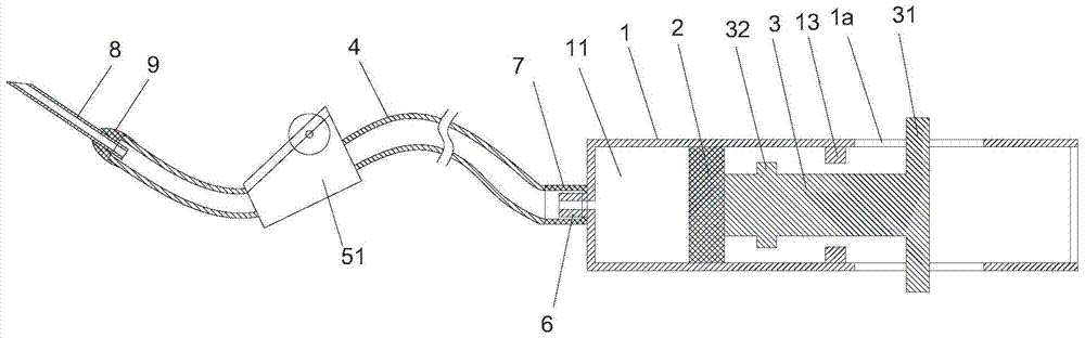
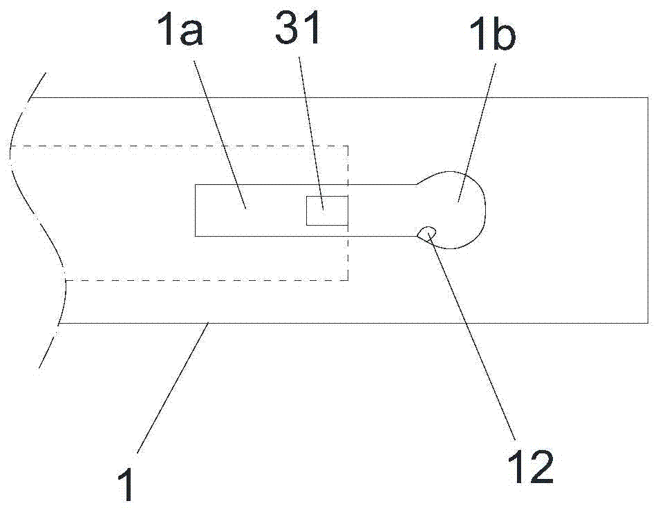
[0021] Such as Figure 1 to Figure 3 Shown: the ophthalmic silicone oil extraction device of this embodiment includes a negative pressure assembly for generating negative pressure and an extraction assembly for extracting silicone oil; The piston 2 and the piston rod 3 in the cavity 11; the extraction assembly includes a conduit 4, and the conduit 4 communicates with the cavity 11; the rod wall of the piston rod 3 is connected with a push-pull part 31, and the cylinder body 1 The cylinder wall is provided with a chute 1a, and the push-pull part 31 passes through the chute 1a, and when the push-pull part 31 slides along the length direction of the chute 1a, it drives the piston rod 3 to move axially along the cavity 11; The cylinder wall of the cylinder 1 is also provided with a limit groove 1b communicating with the chute 1a for limiting the movement of the push-pull member 31; the cylinder 1 has a structure similar to that of the injection cylinder, and the front end of the c...


PUM


Abstract

The invention discloses a silicone oil extracting device for an ophthalmology department. The silicone oil extracting device comprises a negative pressure assembly for generating negative pressure and a extracting assembly for extracting silicone oil; the negative pressure assembly comprise a barrel body with a containing cavity and a piston and a piston rod which are arranged in the containing cavity; the extracting assembly comprises a catheter which is communicated with the containing cavity; the rod wall of the piston rod is connected with a push-pull part, a sliding groove is formed in the barrel wall of the barrel body, the push-pull part penetrates out from the sliding groove, and the push-pull part drives the piston rod to move in the axial direction of the containing cavity when the push-pull part slides in the length direction of the sliding groove; a limit groove which is communicated with the sliding groove and used for limiting movement of the push-pull part is formed in the barrel wall of the barrel body. According to the silicone oil extracting device for the ophthalmology department, the piston rod can be positioned reliably and effectively to prevent an operation from being failed, the pain of a patient is relieved, the structure is simple, and the operation can be conveniently operated.

Description

technical field [0001] The invention relates to an ophthalmic medical device, in particular to an ophthalmic silicone oil removal device. Background technique [0002] Vitrectomy combined with silicone oil intraocular filling for retinal detachment has become a routine clinical operation method. Silicone oil is filled into the patient's eye to support the retinal reset. After the patient's retina is completely reset, the silicone oil in the patient's eye is removed. At present, the medical consumables commonly used in intraocular silicone oil extraction are the silicone oil extraction kits produced by vitrectomy machine manufacturers, which use the continuous negative pressure generated by the vitrectomy machine to remove intraocular silicone oil through the relevant equipment provided by the oil extraction kit. . The price of this medical device is very expensive. In clinical application, the entire operation fee is high, which leads to the high cost of the entire treatmen...

Claims


Application Information

Patent Timeline
Patent Type & Authority Patents(China)
IPC IPC(8): A61F9/007
Inventor 李恒米雪
Owner SUINING CENT HOSPITAL
Why Eureka
Try Eureka