Clamping and pushing device for syringe pump and syringe pump

A technology of a pushing device and a syringe pump, which is applied in the field of syringes, and can solve the problems of immobility, easy failure to use, and easy breakage, etc., and achieve the effect of simple and convenient clamping operation, avoiding fatigue failure, and not easy to damage

Active Publication Date: 2018-07-24
深圳莫微医疗技术有限公司
View PDF5 Cites 0 Cited by
  • Summary
  • Abstract
  • Description
  • Claims
  • Application Information

AI Technical Summary

Problems solved by technology

[0003] The clamping and pushing devices of the existing syringe pumps are generally divided into two types, one is the movable type, that is, the number of claws is two, and each is pivotally connected to the push head, and the two claws are driven to rotate through the gear mechanism Open or snap to release or hold the syringe, but this method has the problem that the claws are easily stuck to viscous liquid medicine such as glucose and cannot move; the other type is fixed, that is, the claws are set to be elastic When clamping the syringe piston handle, the flange at the end of the syringe piston handle needs to be manually inserted between the claw and the push head. At the same time, the root of the claw and the push head will be greatly deformed and bent many times. easy to break or plastic deformation
Therefore, the clamping and pushing device of the syringe pump of the existing syringe pump has the problem of being prone to failure or inconvenient to use

Method used


Image

  • Clamping and pushing device for syringe pump and syringe pump
  • Clamping and pushing device for syringe pump and syringe pump
  • Clamping and pushing device for syringe pump and syringe pump

Examples


Embodiment Construction

[0029] The technical solutions of the present invention will be further described below in conjunction with the accompanying drawings and specific embodiments. It should be understood that the specific embodiments described here are only used to explain the present invention, not to limit the present invention.

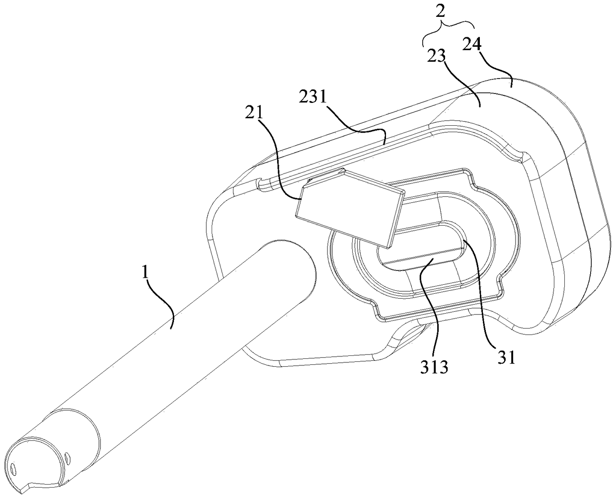
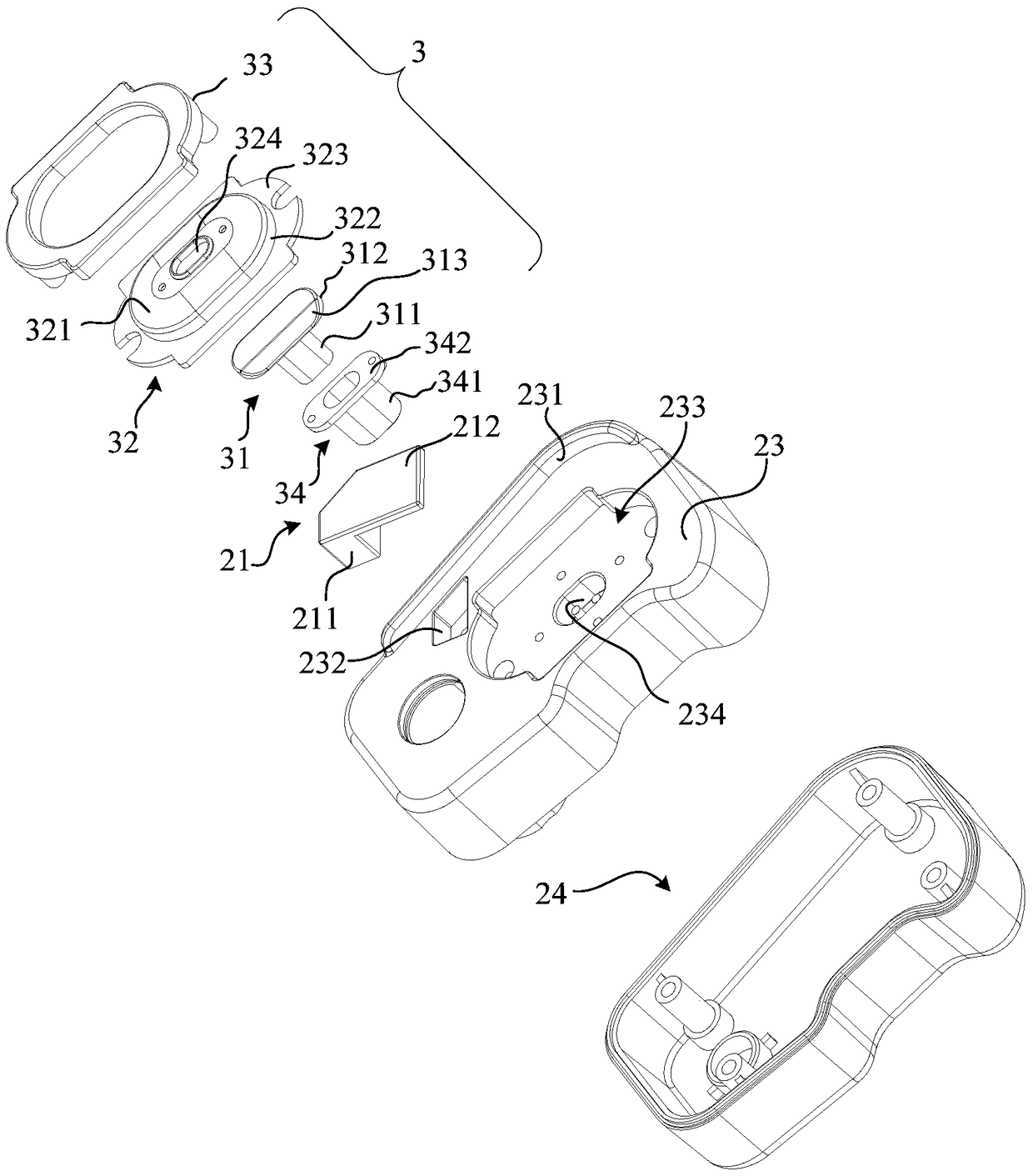
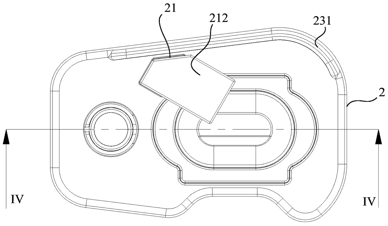
[0030] For the clamping and pushing device of the syringe pump proposed by the present invention, please refer to figure 1 and figure 2 , in one embodiment, the clamping and pushing device 200 of the syringe pump includes a push rod 1 and a push head 2 arranged at one end of the push rod 1; 21 includes a connection portion 211 connected to the push head 2 and a clamping portion 212 connected to the connection portion 211; a clamping gap 22 for clamping the piston handle 301 of the syringe 300 is formed between the clamping portion 212 and the push head 2; The claw 21 rotates with the push head 2 to clamp or release the piston handle 301 .

[0031] In this embodime...


PUM


Abstract

The invention discloses an injection pump clamping and pushing device and an injection pump, wherein the injection pump clamping and pushing device comprises a pushing rod and a pushing head which is arranged at one end of the pushing rod; the pushing head, on the end face facing an injector, is provided with a jaw, and the jaw comprises a connecting part connected to the pushing head and a clamping part connected to the connecting part; a clamping clearance for clamping a piston handle of the injector is formed between the clamping part and the pushing head; and by virtue of the jaw along the rotation of the pushing head, the piston handle is clamped or released. The injection pump clamping and pushing device disclosed by the invention is not easy to become damaged, long in service life, and simple and convenient in clamping operation.

Description

technical field [0001] The invention relates to the technical field of syringes, in particular to a clamping and pushing device for a syringe pump and the syringe pump. Background technique [0002] The syringe pump is an automatic injection device, which mainly realizes automatic injection by precisely controlling the feed of the syringe piston handle. In order to facilitate the clamping of the syringe, the syringe pump generally includes a push rod that can be fed linearly and a push head located at the exposed end of the push rod. The push head is provided with a claw, and the push head and the claw cooperate to clamp the end of the syringe piston handle. flange. [0003] The clamping and pushing devices of the existing syringe pumps are generally divided into two types, one is the movable type, that is, the number of claws is two, and each is pivotally connected to the push head, and the two claws are driven to rotate through the gear mechanism Open or snap to release ...

Claims


Application Information

Patent Timeline
Patent Type & Authority Patents(China)
IPC IPC(8): A61M5/20A61M5/31
Inventor 周杰易燕成王争梁祥锦
Owner 深圳莫微医疗技术有限公司
Why Eureka
Try Eureka