Automatic sponge wrapping device

A sponge, automatic technology, used in packaging, transportation and packaging, packaging/bundling items, etc., can solve the problems of inconsistent quality of sponge packaging, unfavorable production efficiency, large workload, etc., saving manpower and time, maintaining Consistency, the effect of improving production efficiency

Active Publication Date: 2016-02-03
FOSHAN GUANGDONG TECH UNIV CNC EQUIP TECH DEV +1
View PDF5 Cites 7 Cited by
  • Summary
  • Abstract
  • Description
  • Claims
  • Application Information

AI Technical Summary

Problems solved by technology

In the prior art, the wires are still manually wrapped into the sponge strips. For example, thousands of wires need to be wrapped into sponges in the speaker factory every day. The workload is huge, and the staff keeps repeating boring actions. The quality of the sponge packing work completed in different time cannot be consistent, and it consumes a lot of manpower, which is not conducive to improving production efficiency

Method used


Image

  • Automatic sponge wrapping device

Examples


Embodiment Construction

[0018] Below, in conjunction with accompanying drawing and specific embodiment, the present invention is described further:

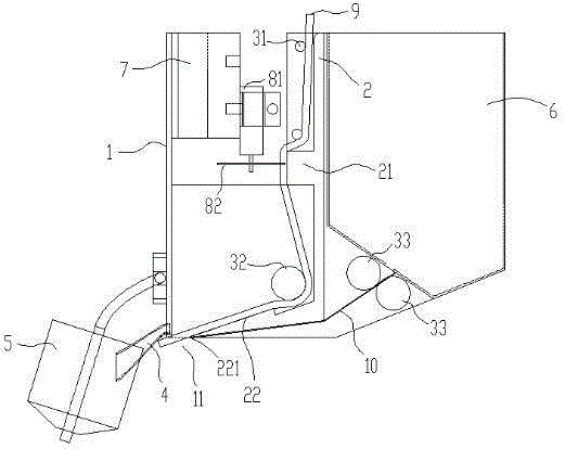
[0019] Such as figure 1 As shown, a kind of automatic bag sponge device comprises casing 1, guide mechanism, traction mechanism, shaping mechanism and cutting mechanism:

[0020] The bottom of the casing 1 is provided with a sponge discharge port 11;

[0021] The guide mechanism arranged in the casing 1 includes a guide plate 2 and a first pressure roller 31 and a second pressure roller 32 pivotally connected to the casing 1 along the width direction of the casing 1. The first pressure roller 31 and the second pressure roller A first gap is formed between the roller 32 and the guide plate 2 for the passage of the sponge strip 9 with the release paper 10. The bottom end of the guide plate 2 is provided with an extension plate 22 extending to the inner side of the sponge discharge port 11. The end of the extension plate 22 away from the guide plate 2 fo...


PUM


Abstract

The invention discloses an automatic sponge wrapping device and relates to the field of production of wires. The automatic sponge wrapping device comprises a device shell, a guiding mechanism, a dragging mechanism and a shaping mechanism. The guiding mechanism comprises a guiding plate, first pressing rollers and a second pressing roller. A first gap allowing sponge bars with release paper to pass through is formed among the first pressing rollers, the second pressing roller and the guiding plate. An extending plate extending to the inner end of a sponge discharging outlet is arranged at the bottom end of the guiding plate, an ejecting and pressing portion used for ejecting and pressing the sponge bars with the release paper is arranged at the end, away from the guiding plate, of the extending plate, and the second pressing roller is located at the end, away from the ejecting and pressing portion, of the upper portion of the extending plate. The dragging mechanism is arranged at the end, away from the ejecting and pressing portion, of the lower portion of the extending plate. The shaping mechanism comprises a flexible shaping plate and two extrusion rollers, and the extrusion rollers are pivoted to the device shell and used for extruding the end, away from the device shell, of the flexible shaping plate into an inverse U shape. The wires are wrapped by the sponge bars by the automatic sponge wrapping device replacing manpower, and production efficiency is improved.

Description

technical field [0001] The invention relates to the field of wire production, in particular to an automatic sponge wrapping device. Background technique [0002] On the market, the wires in many instruments, including speakers, need to be covered with a layer of sponge to prevent shock and damage. The sponge used is a sponge sticker with self-adhesive, which is sticky on one side. Use release paper to protect the stickiness before wrapping the wire, and remove the release paper before wrapping the wire. In the prior art, the wires are still manually wrapped into the sponge strips. For example, thousands of wires need to be wrapped into sponges in the speaker factory every day. The workload is huge, and the staff keeps repeating boring actions. The quality of the sponge-packing work completed in different time periods cannot be consistent, and consumes a lot of manpower, which is not conducive to improving production efficiency. [0003] The linear slide rail cylinder inclu...

Claims


Application Information

Patent Timeline
Patent Type & Authority Applications(China)
IPC IPC(8): B65B11/02B65B61/06
CPCB65B11/02B65B61/06
Inventor 李柏燐
Owner FOSHAN GUANGDONG TECH UNIV CNC EQUIP TECH DEV
Why Eureka
Try Eureka