Automatic Bundling Pipe Bagging Machine

An automatic strapping and bagging machine technology, which is applied in the direction of strapping materials, strapping machine parts, external supports, etc., can solve the problems of large space occupation, inconvenience for workers to move equipment, long packaging time, etc., and achieve small footprint , Save the transshipment process, the effect of high degree of automation

Active Publication Date: 2018-06-22
GUANGDONG LIANSU MACHINERY MFG
View PDF4 Cites 9 Cited by
  • Summary
  • Abstract
  • Description
  • Claims
  • Application Information

AI Technical Summary

Problems solved by technology

[0002] Nowadays, the development of domestic pipe packaging technology is still relatively slow. The packaging of pipes needs to go through two necessary processes of bundling and bagging, and most manufacturers of these two processes need manual intervention. The degree of automation is not high, which also increases the workload of workers; although some manufacturers have produced automatic packaging equipment for pipes, due to the many processes involved, especially the two processes of bundling and bagging, the existing equipment cannot do it. To the coherent processing of the coaxial line, the binding and bagging are carried out at staggered stations. Generally, the bagging device is located in front of the binding device, so the pipe needs to be transported to the bagging workers of different axes through the conveying device after the binding is completed at the binding station. The position is bagged, which makes the equipment relatively large and takes up a lot of space on the site. Moreover, after the pipe is packed, the pipe must be unloaded to the loading rack, and the loading rack takes up a certain space, resulting in the space between the equipment. The aisle is narrow, which is inconvenient for workers to pass through and other equipment to move, so such equipment is not suitable for mass packaging of equipment in a limited space.

Method used


Image

  • Automatic Bundling Pipe Bagging Machine
  • Automatic Bundling Pipe Bagging Machine
  • Automatic Bundling Pipe Bagging Machine

Examples


Embodiment

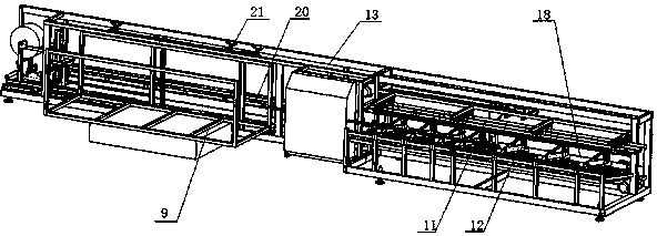
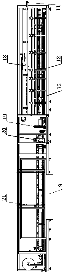
[0046] Such as figure 1 and figure 2 As shown, an automatic binding pipe bagging machine includes a frame 13, and the frame 13 is provided with a turning frame 11 and a material holding and pressing mechanism 12, and the turning frame 11 is located above the holding and pressing material 12 , used to introduce the pipes to be bundled and bagged outside, and turn the pipes into the holding and pressing mechanism 12, which is used to control the orderly rolling of the pipes, and the back of the holding and pressing mechanism 12 is from From right to left, a pushing mechanism 18, a binding mechanism 19 and a bagging mechanism 20 are arranged on the same horizontal axis in sequence. Under the push of the pushing mechanism 18, the pipes are first bundled in the binding mechanism 19, and then bagged in the bagging mechanism 20. , the pipe after bagging is unloaded into the external charging rack 22 through the liftable unloading mechanism 21 .

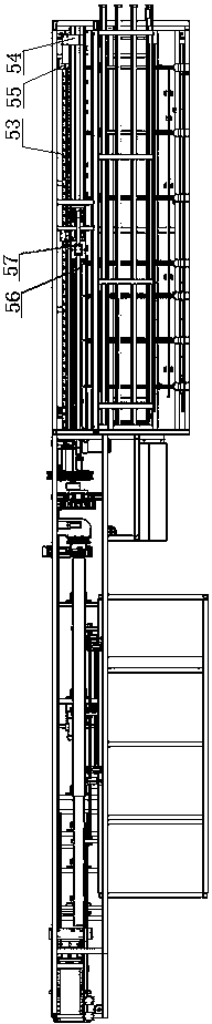
[0047] Such as image 3 , Figur...


PUM


Abstract

The invention discloses an automatic pipe bundling and bagging machine which comprises a machine frame. A turnover frame and a supporting and pressing mechanism are arranged on the machine frame. The turnover frame is located on the supporting and pressing mechanism and used for leading in outside pipes to be bundled and bagged and turning the pipes into the supporting and pressing mechanism. The supporting and pressing mechanism is used for controlling the pipes to roll in sequence. A pushing mechanism, a bundling mechanism and a bagging mechanism are sequentially arranged behind the supporting and pressing mechanism from right to left and located on the same horizontal axis. The pipes are pushed by the pushing mechanism to be firstly bundled by the bundling mechanism and then bagged by the bagging mechanism. The bagged pipes can be discharged into an outside storage rack through a lifting discharging mechanism. The automatic pipe bundling and bagging machine is high in automation degree, and coherent processing of bundling and bagging on the same axis is achieved; besides, the whole machine is small in occupied space so that a large batch of machines can carry out pipe packaging in a concentrated mode.

Description

technical field [0001] The invention belongs to the field of pipe bundling and bagging, in particular to an automatic bundling pipe bagging machine. Background technique [0002] Nowadays, the development of domestic pipe packaging technology is still relatively slow. The packaging of pipes needs to go through two necessary processes of bundling and bagging, and most manufacturers of these two processes need manual intervention. The degree of automation is not high, which also increases the workload of workers; although some manufacturers have produced automatic packaging equipment for pipes, due to the many processes involved, especially the two processes of bundling and bagging, the existing equipment cannot do it. To the coherent processing of the coaxial line, the binding and bagging are carried out at staggered stations. Generally, the bagging device is located in front of the binding device, so the pipe needs to be transported to the bagging workers of different axes t...

Claims


Application Information

Patent Timeline
Patent Type & Authority Patents(China)
IPC IPC(8): B65B35/40B65B35/32B65B13/20B65B13/10B65B61/10B65B43/46B65B51/14
CPCB65B13/10B65B13/20B65B35/32B65B35/40B65B43/465B65B51/146B65B61/10
Inventor 王泽清
Owner GUANGDONG LIANSU MACHINERY MFG
Why Eureka
Try Eureka