
Movable, liftable and telescopic belt conveying weigher

A technology of belt conveyor and belt conveyor, which is applied in the field of mobile lifting and telescopic belt conveyor scales, to achieve the effect of increasing the application range, ensuring stability, and solving the problem of fixed and non-movable positions

Active Publication Date: 2016-02-03
COFCO ENG MAOSHENG EQUIP (HENAN) CO LTD
View PDF9 Cites 5 Cited by
  • Summary
  • Abstract
  • Description
  • Claims
  • Application Information

AI Technical Summary

Problems solved by technology

[0003] However, most of the existing belt scales are fixed belt scales, that is, the position of the belt scale is generally immovable. Move to the location of the belt scale on the belt conveyor. In addition, after the installation of the existing belt scale is completed, its height and direction are fixed and cannot be changed, which limits the application range of the belt scale. weighing, the material must be transported to the location where the belt scale is located

Method used


Image

  • Movable, liftable and telescopic belt conveying weigher
  • Movable, liftable and telescopic belt conveying weigher
  • Movable, liftable and telescopic belt conveying weigher

Examples


Embodiment 1

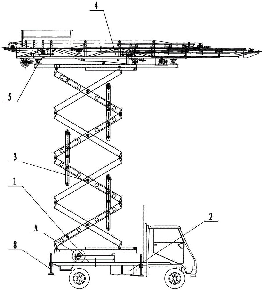
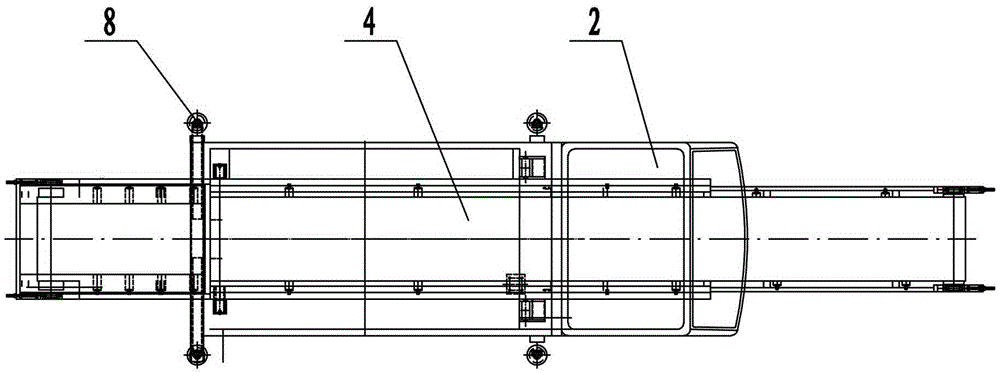
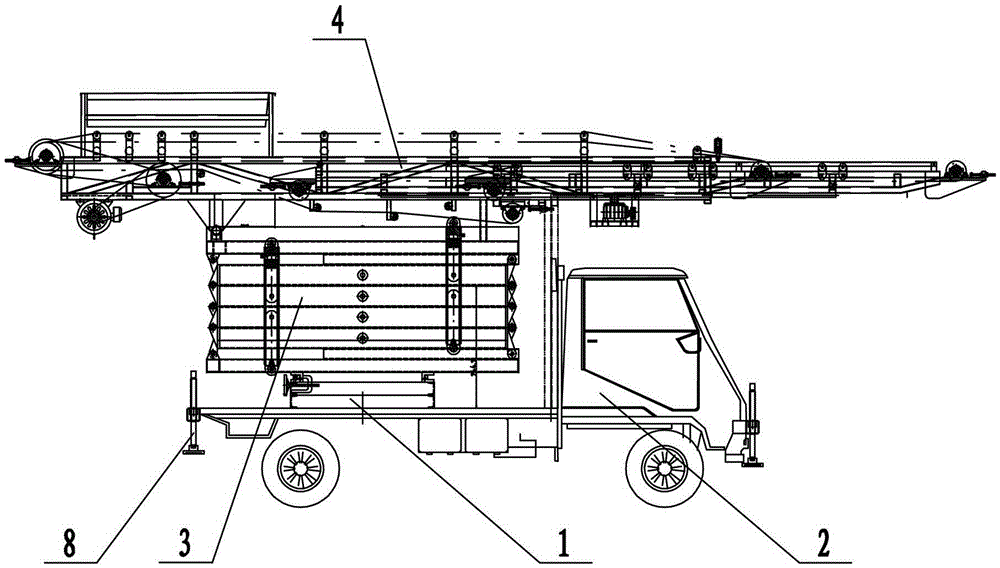
[0027] Such as figure 1 , figure 2 , image 3 , Figure 4 As shown, a mobile lifting and telescopic belt conveyor scale includes a base 1, a moving mechanism 2, a lifting frame 3, a belt conveyor 4, and a sensor speed measurement weighing measurement system 5, and the lower end of the base 1 is fixed on the moving mechanism 2 Above, the mobile mechanism 2 is a motor vehicle, the base 1 is fixed on the motor vehicle, and the front and rear ends of the motor vehicle are provided with liftable outriggers 8, which can enable the positioning and stability of the mobile mechanism 2. The upper end of the base 1 is connected to the lifting The lower ends of the frame 3 are mutually rotatably connected by a rotating mechanism. The lifting frame 3 is a hydraulic lifting frame 3, and the rotating mechanism includes a lower ring 9 fixed on the upper end of the base 1, an upper ring 10 fixed on the lower end of the hydraulic lifting frame 3, and an upper ring 10 fixed on the lower end ...

Embodiment 2

[0034] Such as Figure 5 As shown, the first embodiment is repeated, with the following differences. In this embodiment, the lower end of the base 1 is fixed on the trolley 6, and the trolley 6 is pulled by the traction locomotive to move, so that the belt conveyor scale of the present invention can be moved. Scalable supporting legs 8 are arranged on the four corners of dolly 6, and tractor locomotive can be selected tractor or other manual machinery for use.


PUM


Abstract

The invention provides a movable, liftable and telescopic belt conveying weigher. The movable, liftable and telescopic belt conveying weigher comprises a base, a moving mechanism, a lifting frame, a belt conveyer, and a sensing, speed measurement and weighing measurement system, wherein the lower end of the base is fixed on the moving mechanism; the upper end of the base is in mutual rotating connection with the lower end of the lifting frame; the sensing, speed measurement and weighing measurement system is fixed at the upper end of the lifting frame; the belt conveyer is arranged on the sensing, speed measurement and weighing measurement system; and the belt conveyer is a telescopic belt conveyer. The belt weigher provided by the invention is placed on the movable base, and movability of the belt weigher can be realized through a traction engine; the hydraulic lifting frame is arranged between the belt weigher and the base, thus lifting and height adjustment for the belt weigher are realized; the lower end of the hydraulic lifting frame of the belt weigher provided by the invention is in mutual rotating connection with the base, thus angle rotation for the belt weigher is realized, and the working direction of the belt weigher is adjusted; and the telescopic belt conveyer is used as the conveyer for the belt weigher for realizing telescoping of the belt weigher and adjustability of a conveying distance.

Description

Technical field: [0001] The invention belongs to the technical field of transportation and conveying machinery equipment, and in particular relates to a mobile lifting telescopic belt conveying scale. Background technique: [0002] A belt scale refers to a weighing instrument that automatically weighs loose materials that are placed on a belt and pass continuously with the belt. The weighing bridge of the belt scale is installed on the conveyor frame. When the material passes by, the weighing roller detects the weight of the material on the belt conveyor and acts on the load cell through leverage to generate a voltage signal proportional to the belt load. There is a weighing sensor installed on the weighing bridge on the belt scale. When working, the detected material weight on the belt is sent to the weighing instrument, and the speed signal of the belt conveyor from the speed sensor is also sent to the weighing instrument. The instrument integrates the speed signal and ...

Claims


Application Information

Patent Timeline
Patent Type & Authority Applications(China)
IPC IPC(8): B65G41/00B65G21/10
Inventor 赵治永叶伟男聂运强朱金秋郭江伟张法行朱明俊孟青青
Owner COFCO ENG MAOSHENG EQUIP (HENAN) CO LTD
Learn More