Automatic line distribution and collecting device

A technology of automatic wiring and wire take-up, applied in the field of wire take-up

Inactive Publication Date: 2016-02-03
CHONGQING LIANGNENG MACHINERY CO LTD
View PDF1 Cites 3 Cited by
  • Summary
  • Abstract
  • Description
  • Claims
  • Application Information

AI Technical Summary

Problems solved by technology

[0004] However, the disadvantage of this technical solution is that the power to drive the take-up reel to rotate and to drive the take-up reel to reciprocat

Method used


Image

  • Automatic line distribution and collecting device

Examples


Embodiment 1

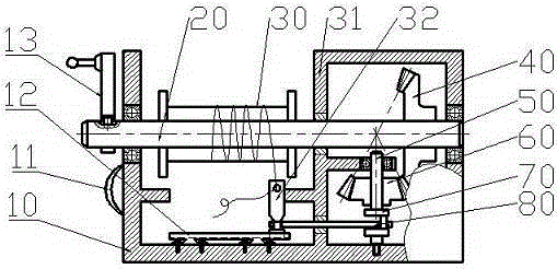
[0014] like figure 1 As shown, the automatic wiring take-up device includes: a base 10 , a take-up reel 30 , and a power shaft 20 . Two sidewalls of the base 10 are provided with symmetrical holes, and bearings are installed in the holes. A handle 11 is also installed on the outward side of the side wall of the base 10 . The take-up reel 30 is sleeved on the power shaft 20 and rotates with the power shaft 20 . Also includes driving helical gear 40, driven shaft 50, driven helical gear 60, eccentric wheel 70, connecting rod 80, wiring disc 32, chute 12; driving helical gear 40 is sleeved on the power shaft 20; driven shaft 50 Located below the driving helical gear 40, the driven helical gear 60 is sleeved on the driven shaft 50 and cooperates with the driving helical gear 40. An eccentric wheel 70 is connected below the driven shaft 50; the lower part of the eccentric wheel 70 is connected to the base 10 The bottom is hinged; the chute 12 is located below the take-up reel 30...


PUM


Abstract

The invention relates to the field of line collecting devices, and discloses an automatic line distribution and collecting device. According to the scheme, the automatic line distribution and collecting device comprises a base, a line collecting disc and a power shaft, wherein the power shaft is horizontally arranged on the base; the line collecting disc is arranged on the power shaft. The automatic line distribution and collecting device further comprises a driving bevel wheel, a driven shaft, a driven bevel wheel, an eccentric wheel, a connecting rod, a line distribution disc and a sliding disc, wherein the driving bevel wheel is arranged on the power shaft in a sleeving mode; the driven shaft is located below the driving bevel wheel; the driven bevel wheel is arranged on the driven shaft in a sleeving mode and matched with the driving bevel wheel; the eccentric wheel is connected under the driven shaft; the lower portion of the eccentric wheel is hinged to the bottom of the base; the sliding groove is located below the line collecting disc and connected with the bottom of the base; the lower portion of the line distribution disc is matched with the sliding groove in shape and located in the sliding groove, and the upper portion of the line distribution disc is provided with a hole; one end of the connecting rod is hinged to the eccentric wheel, and the other end of the connecting rod is hinged to the line distribution disc. The automatic line distribution and collecting device can automatically collect and distribute line with a single power source.

Description

technical field [0001] The invention relates to the field of wire take-ups, in particular to an automatic wiring take-up. Background technique [0002] At present, in the process of engineering construction, when collecting electric wires, iron wires or other cords, it is generally done manually, and the labor efficiency is not high. Secondly, in the existing electromagnetic wire production process, from the production of raw materials to the final product molding, a large number of operations are also carried out manually relying on personal operating experience, and the use of proprietary equipment is less, resulting in more unstable factors in product quality . [0003] The patent with the publication number CN103991751A discloses a wire take-up device. Its technical solution is: it includes a base, a movable plate, a wire take-up bracket and a wire take-up reel. Slide rails are distributed on the base, and the movable plate moves along the slide rail. The rail is slida...

Claims


Application Information

Patent Timeline
IPC IPC(8): B65H54/28
Inventor 李天能
Owner CHONGQING LIANGNENG MACHINERY CO LTD
Why Eureka
Try Eureka