Material box for microwave heating
A microwave heating and material box technology, which is applied in food heating containers, lighting and heating equipment, applications, etc., can solve the problems of low heating efficiency, increased energy consumption of soil microwave thermal desorption, and high use costs, so as to reduce the use cost, The effect of improving electromagnetic field distribution and heating efficiency
- Summary
- Abstract
- Description
- Claims
- Application Information
AI Technical Summary
Problems solved by technology
Method used
Image
Examples
Embodiment 1
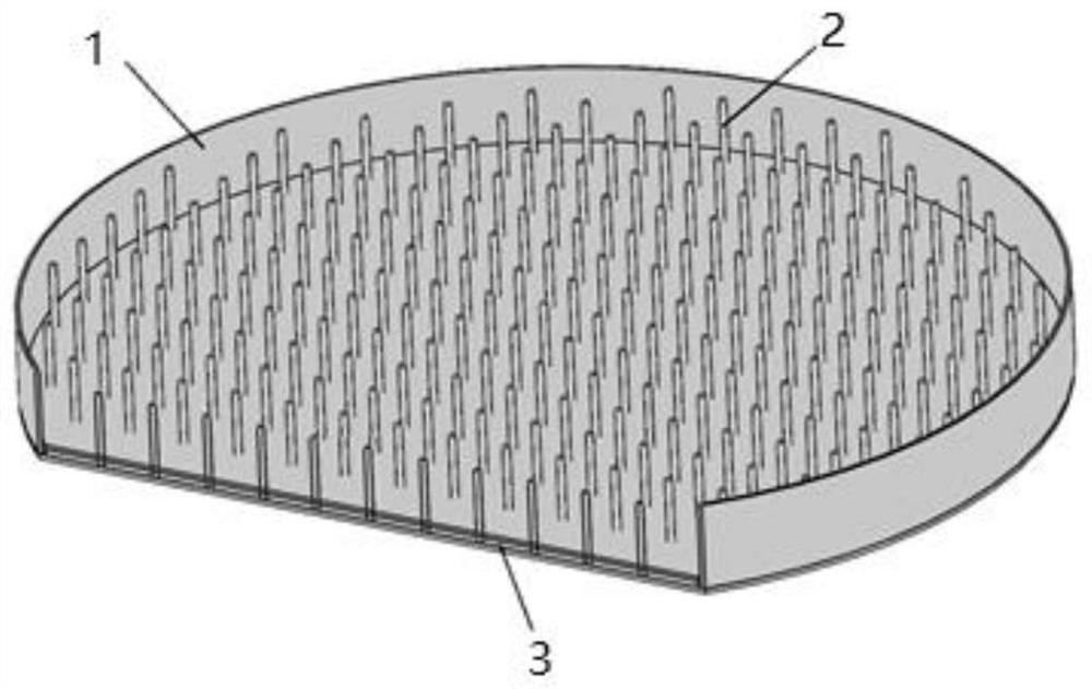
[0020] Such as figure 1 As shown, the shape of the material box 1 is a hollow cylinder without an upper bottom surface, its height is 105 mm, its bottom surface diameter is 860 mm, its material is metal, and an insulating heat-preservation layer 3 is provided on the lower bottom surface in the material box. Electrodes 2 are arranged on the insulation layer 3 .
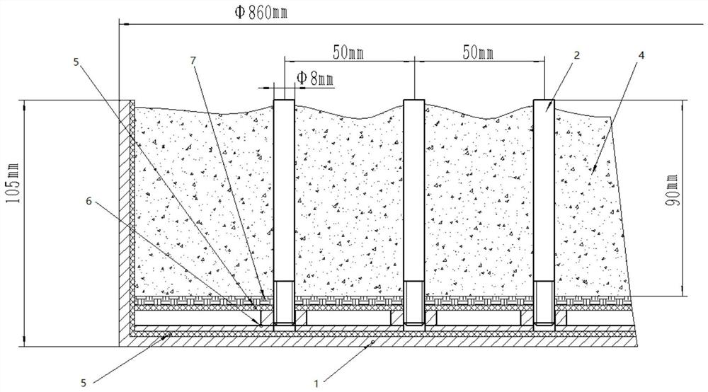
[0021] Such as figure 2 As shown, the insulation and heat preservation layer 3 includes asbestos cloth 5 arranged from bottom to top, an insulation fixing plate 6 and asbestos cloth 5, graphite felt 7 is also arranged on the insulation and heat preservation layer 3, and graphite felt 7 is arranged on the insulation fixing plate 6. There are threaded holes for fixing the electrodes, and the distance between every two adjacent threaded holes is 50 mm. One end of the electrode 2 is processed with threads, which pass through the graphite felt 7 and the asbestos cloth 5 to connect with the insulating fixing plate 6 . A l...
Embodiment 2
[0024] Such as figure 1 and image 3 As shown, the shape of the material box 1 is a hollow cylinder without an upper bottom surface, its height is 105mm, its bottom surface diameter is 860mm, its material is metal, and an asbestos cloth 5 is arranged on the lower bottom surface in the material box, so Graphite felt 7 is arranged on the asbestos cloth 5, and electrodes 2 are arranged on the graphite felt.
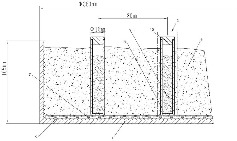
[0025] Such as image 3 As shown, the inner surface around the side wall of the material box 1 is covered with a layer of asbestos cloth 5, so that the material box 1 is insulated from the heating material 4. The electrode includes a ceramic body and the medium filled therein. The ceramic body includes a ceramic tube 8 and a ceramic cover 10. The ceramic tube 8 and the ceramic cover 10 form a hollow cylindrical structure with a bottom diameter of 16 mm. The medium 9 is copper powder or graphite powder or ceramic powder, which is filled inside the ceramic tube 8 . The bot...
Embodiment 3
[0028] Such as figure 1 and Figure 4 As shown, the shape of the material box 1 is a hollow cylinder without an upper bottom surface, its height is 105mm, its bottom surface diameter is 860mm, its material is metal, and an asbestos cloth 5 is arranged on the lower bottom surface in the material box, so Graphite felt 7 is arranged on the asbestos cloth 5, and electrodes 2 are arranged on the graphite felt.
[0029] Such as Figure 4 As shown, the inner surface around the side wall of the material box 1 is covered with a layer of asbestos cloth 5, so that the material box 1 is insulated from the heating material 4. The electrode includes a ceramic body and the medium filled therein. The ceramic body includes a ceramic tube 8 and a ceramic cover 10. The ceramic tube 8 and the ceramic cover 10 form a hollow cylindrical structure with a bottom diameter of 16 mm. The medium 9 is copper powder or graphite powder or ceramic powder, which is filled inside the ceramic tube 8 . A lay...
PUM
| Property | Measurement | Unit |
|---|---|---|
| diameter | aaaaa | aaaaa |
| height | aaaaa | aaaaa |
| diameter | aaaaa | aaaaa |
Abstract
Description
Claims
Application Information
 - R&D
- Intellectual Property
- Life Sciences
- Materials
- Tech Scout
- Unparalleled Data Quality
- Higher Quality Content
- 60% Fewer Hallucinations
Browse by: Latest US Patents, China's latest patents, Technical Efficacy Thesaurus, Application Domain, Technology Topic, Popular Technical Reports.
© 2025 PatSnap. All rights reserved.Legal|Privacy policy|Modern Slavery Act Transparency Statement|Sitemap|About US| Contact US: help@patsnap.com


