Over-speed governor and using method thereof

A technology of a speed limiter and a brake arm, which is applied to elevators, transportation and packaging, etc., can solve the problems such as the inability of the moving brake parts 17 to fall and the parts fail, and achieve the effects of simple structure, improved life, and convenient operation.

Active Publication Date: 2016-02-03
乐天电梯部件(浙江)有限公司
View PDF6 Cites 9 Cited by
  • Summary
  • Abstract
  • Description
  • Claims
  • Application Information

AI Technical Summary

Problems solved by technology

[0012] Figure 4 Also have the following characteristics: when the angle a1 of the dynamic braking component 17 and the horizontal direction is improperly set, it is easy to produce the situation that the dynamic braking component 17 cannot fall; 17 will disengage again, causing component failure

Method used


Image

  • Over-speed governor and using method thereof
  • Over-speed governor and using method thereof
  • Over-speed governor and using method thereof

Examples


Embodiment 1

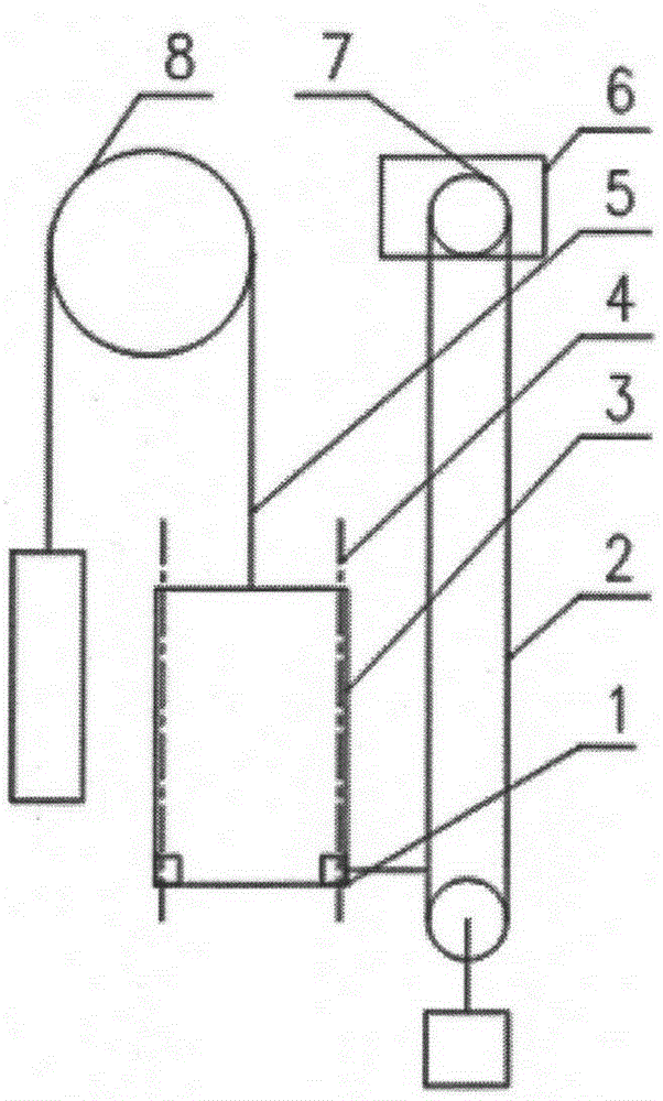
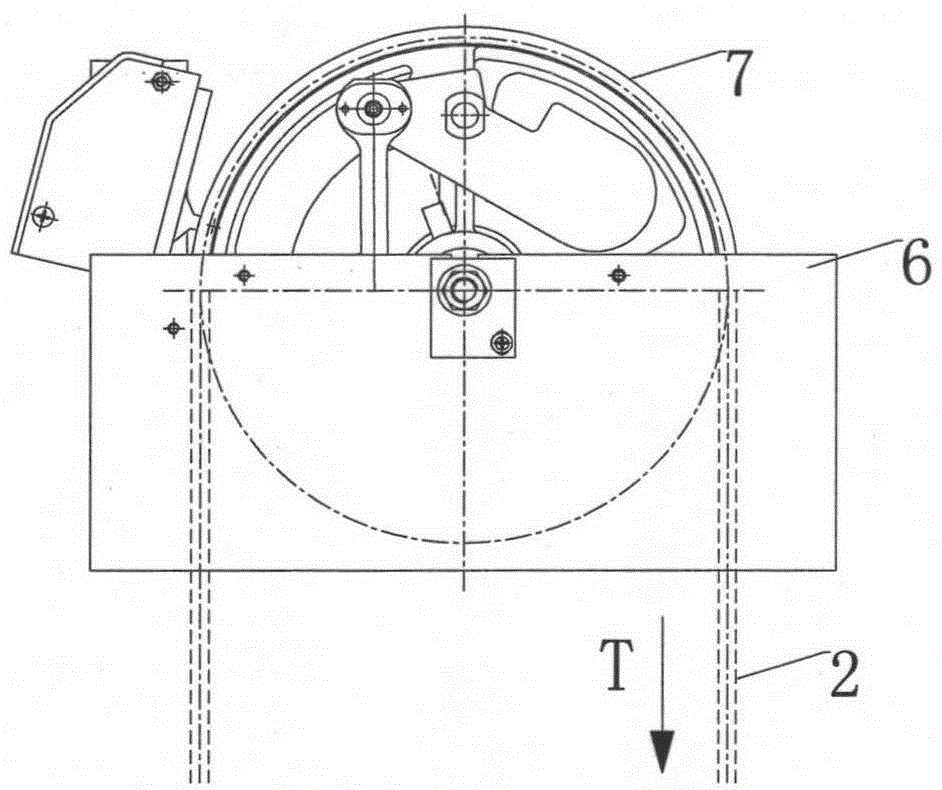
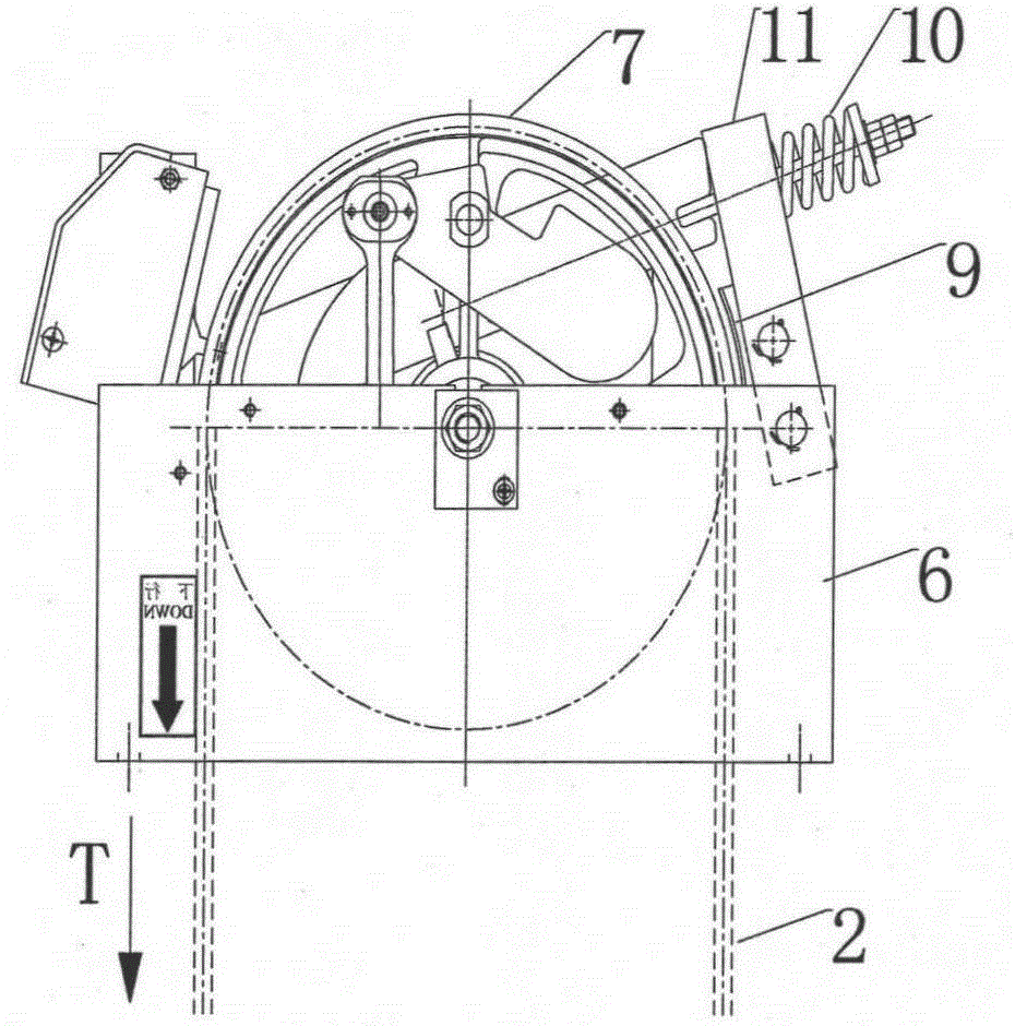
[0053] Figure 5 ~ Figure 7 Shown is a schematic diagram of the overall structure of the speed limiter provided by the present invention, which is the state before triggering. The speed limiter includes a bottom plate 32, and a front side plate 33 and a rear side plate 34 respectively arranged on the front and rear sides of the bottom plate 32; Be provided with sheave assembly 7 in the middle of front side plate 33, rear side plate 34, combine Figure 10 , the rope wheel assembly 7 rotates around the main shaft 39; in the middle of the front side plate 33 and the rear side plate 34, a ratchet 14 rotating around the main shaft 39, a driving wheel 18 and a pawl 35 matched with the ratchet 14, the driving wheel 18 and the ratchet 14 rotate synchronously; on the left side of the sheave assembly 7, a brake arm 23, a static brake block 28 and a dynamic brake block 27 are provided; a trigger lever 25 is arranged at a position equal to the main shaft 39, and one end of the trigger lev...

Embodiment 2

[0065] combine Figure 12 , this embodiment is substantially the same as Embodiment 1, the difference is that the manual trigger lever 38 is canceled on the basis of Embodiment 1, and a reset lever 42 is added to the brake arm 23 at the same time, so that the force arm is increased, and when the speed limiter is reset Manpower is applied to the far end of the reset lever 42. When the reset lever 42 rotates counterclockwise, the brake arm 23 is driven to rotate counterclockwise, and the rotating shaft 26 is driven to rotate around the second brake shaft 31 at the same time. At this time, under the action of the torsion spring 36 Next, the trigger lever 25 rotates counterclockwise around the rotating shaft 26. When the trigger lever 25 touches the limit pin 24, release the reset lever 42, and then reset the electric switch 19 to complete all resets.

Embodiment 3

[0067] combine Figure 13 , the brake arm 23 in embodiment 1 and embodiment 2 only works when the sheave assembly 7 overspeeds in the counterclockwise direction. function, the specific method is:

[0068] On the basis of embodiment 2, the ratchet 14 is set as a two-way ratchet, and the pawl 35 is set as a two-way pawl. In order to keep the trigger lever 25 in a horizontal position at ordinary times, a holding torsion spring 44 is added at the end of the trigger lever 25. The specific working process It is: when the rope wheel assembly 7 is overspeeding in the counterclockwise direction, the action process is the same as that of embodiment 1. When the rope wheel assembly 7 is overspeeding in the clockwise direction, the pawl 35 falls to drive the ratchet 14 to rotate clockwise, and at the same time drives the trigger lever 25 to rotate counterclockwise around the rotating shaft 26. Clockwise rotation, when the trigger lever 25 rotates until the balance is broken, the brake arm...


PUM


Abstract

The invention provides an over-speed governor. The over-speed governor comprises a base plate and lateral plates arranged on the two sides of the base plate; a rope wheel assembly, a ratchet wheel and a driving wheel which can rotate around a main shaft are arranged between the two lateral plates; a brake arm is arranged on the lateral face of the rope wheel assembly, one end of a trigger rod equal to the main shaft in height is connected with the brake arm through a rotating shaft, and the other end of the trigger rod is in contact with the driving wheel; one end of the brake arm is connected with one end of a pull rod, and the other end of the brake arm is connected with a fixed brake block and a movable brake block; and the other end of the pull rod is provided with a mechanical switch, and the pull rod is provided with a spring in the compression energy-storage state under the normal condition. The invention further provides a using method of the over-speed governor. The over-speed governor has an overspeed protection function, and can move at a speed lower than a nominal speed; after the over-speed governor moves, the rope wheel assembly and a steel wire rope do not slide relatively, and the service life of a wheel groove of the rope wheel assembly is greatly prolonged; and the ratchet wheel can be located at any position on the periphery during resetting, operation is convenient, reliability is high, and the application field of the over-speed governor is widened.

Description

technical field [0001] The invention relates to the technical field of elevator safety, in particular to a speed governor for triggering an elevator safety actuator or device. Background technique [0002] Article 4.67 of GB / T7024-1997 "Terminology for Elevators, Escalators, and Moving Walks" defines the speed limiter as a safety device that can cause the safety gear to work when the running speed of the elevator exceeds a certain value of the rated speed of the elevator. It can be seen from the definition that the speed limiter is a kind of elevator overspeed protection device, and its function is to send a signal to the safety actuator to protect the elevator when it detects the elevator overspeed. [0003] At present, the existing speed limiter is generally installed in the elevator equipment room, and usually adopts the principle of centrifugal throwing blocks, such as figure 1 As shown, the car 3 located in the guide rail 4 drives the speed governor sheave assembly 7 t...

Claims


Application Information

Patent Timeline
Patent Type & Authority Applications(China)
IPC IPC(8): B66B5/04
CPCB66B5/044
Inventor 徐东升邹智曾庆埔张冲
Owner 乐天电梯部件(浙江)有限公司
Why Eureka
Try Eureka