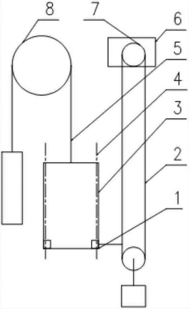
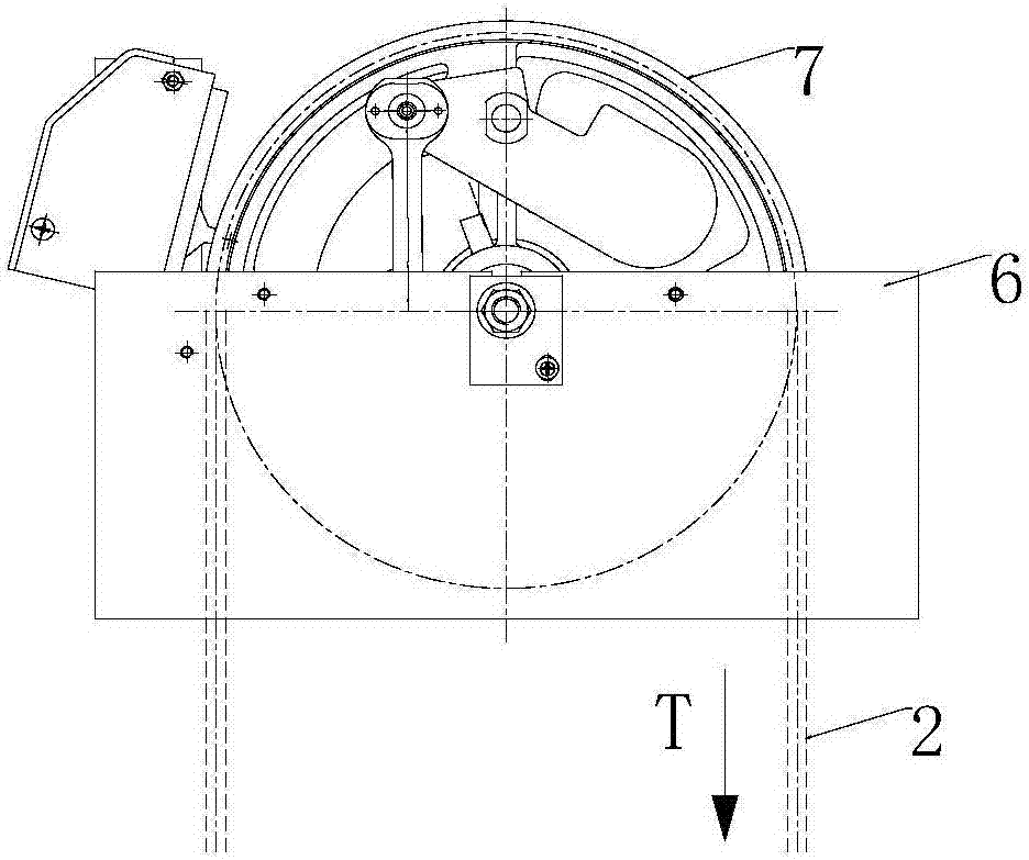
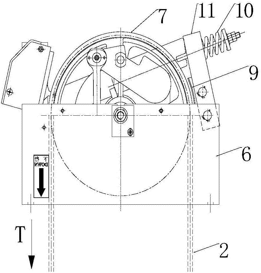
A kind of speed limiter and using method thereof
A technology of speed limiter and brake arm, which is used in elevators, transportation and packaging, etc., can solve the problems such as the inability of the moving brake parts 17 to fall, the failure of parts, etc., and achieve the effects of simple structure, improved life, and high reliability.
- Summary
- Abstract
- Description
- Claims
- Application Information
AI Technical Summary
Problems solved by technology
Method used
Image
Examples
Embodiment 1
[0053] Figure 5 ~ Figure 7 Shown is a schematic diagram of the overall structure of the speed limiter provided by the present invention, which is the state before triggering. The speed limiter includes a bottom plate 32, and a front side plate 33 and a rear side plate 34 respectively arranged on the front and rear sides of the bottom plate 32; Be provided with sheave assembly 7 in the middle of front side plate 33, rear side plate 34, combine Figure 10 , the rope wheel assembly 7 rotates around the main shaft 39; in the middle of the front side plate 33 and the rear side plate 34, a ratchet 14, a driving wheel 18 and a pawl matching the ratchet 14, the driving wheel 18 and the ratchet 14 are also provided. Rotate synchronously; a brake arm 23, a static brake block 28 and a dynamic brake block 27 are provided on the left side of the rope wheel assembly 7; Connect with the brake arm 23, the other end of the trigger lever 25 is in contact with the drive wheel 18. Under normal ...
Embodiment 2
[0065] combine Figure 12 , this embodiment is substantially the same as Embodiment 1, the difference is that the manual trigger lever 38 is canceled on the basis of Embodiment 1, and a reset lever 42 is added to the brake arm 23 at the same time, so that the force arm is increased, and when the speed limiter is reset Manpower is applied to the far end of the reset lever 42. When the reset lever 42 rotates counterclockwise, the brake arm 23 is driven to rotate counterclockwise, and the rotating shaft 26 is driven to rotate around the second brake shaft 31 at the same time. At this time, under the action of the torsion spring 36 Next, the trigger lever 25 rotates counterclockwise around the rotating shaft 26. When the trigger lever 25 touches the limit pin 24, release the reset lever 42, and then reset the electric switch 19 to complete all resets.
Embodiment 3
[0067] combine Figure 13 , the brake arm 23 in embodiment 1 and embodiment 2 only works when the sheave assembly 7 overspeeds in the counterclockwise direction. function, the specific method is:
[0068] On the basis of embodiment 2, the ratchet 14 is set as a two-way ratchet, and the pawl is set as a two-way pawl. In order to keep the trigger lever 25 in a horizontal position at ordinary times, a holding torsion spring 44 is added at the end of the trigger lever 25. The specific working process is as follows: : When the rope wheel assembly 7 overspeeds in the counterclockwise direction, the action process is the same as in embodiment 1. When the rope wheel assembly 7 overspeeds in the clockwise direction, the pawl falls to drive the ratchet 14 to rotate clockwise, and simultaneously drives the trigger lever 25 to rotate counterclockwise around the rotating shaft 26 , when the trigger lever 25 is rotated until the balance is broken, the brake arm 23 will press the steel wire...
PUM
 Abstract
Description
Claims
Application Information
 - R&D
- Intellectual Property
- Life Sciences
- Materials
- Tech Scout
- Unparalleled Data Quality
- Higher Quality Content
- 60% Fewer Hallucinations
Browse by: Latest US Patents, China's latest patents, Technical Efficacy Thesaurus, Application Domain, Technology Topic, Popular Technical Reports.
© 2025 PatSnap. All rights reserved.Legal|Privacy policy|Modern Slavery Act Transparency Statement|Sitemap|About US| Contact US: help@patsnap.com


