Electric valve

An electric valve and valve seat technology, which is applied to valve devices, valve details, engine components, etc., can solve the problems of high production cost, high product cost, complicated manufacturing process, etc., and achieve production cost and product cost restraint and discharge restraint. phenomenon, the effect of reducing adverse effects

Active Publication Date: 2016-02-03
FUJIKOKI MFG CO LTD
View PDF7 Cites 9 Cited by
  • Summary
  • Abstract
  • Description
  • Claims
  • Application Information

AI Technical Summary

Problems solved by technology

To modify the existing stator, etc., it is necessary to change the shape of the existing molding die, etc., which may complicate the manufacturing process and increase the production cost and product cost.

Method used


Image

  • Electric valve
  • Electric valve
  • Electric valve

Examples


Embodiment Construction

[0058] Embodiments of the present invention will be described below with reference to the accompanying drawings.

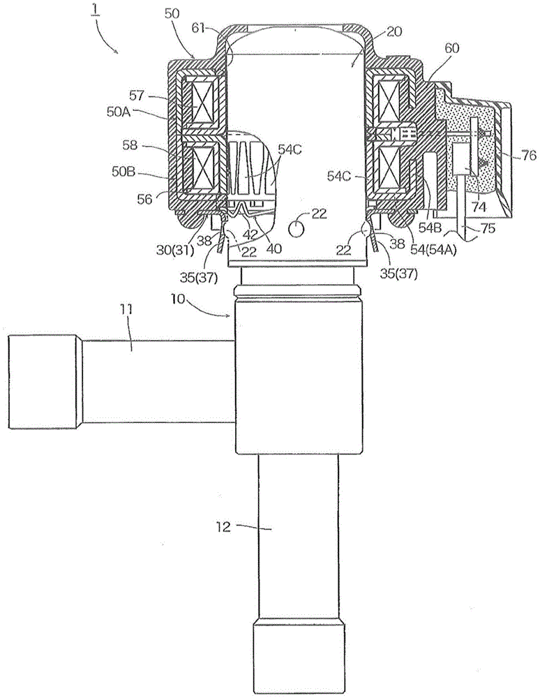
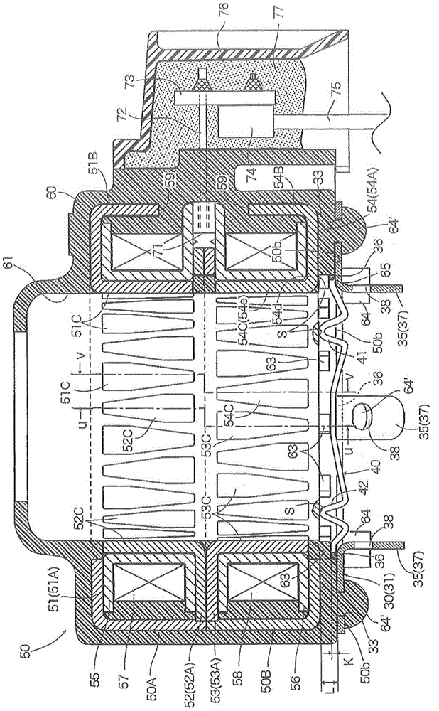
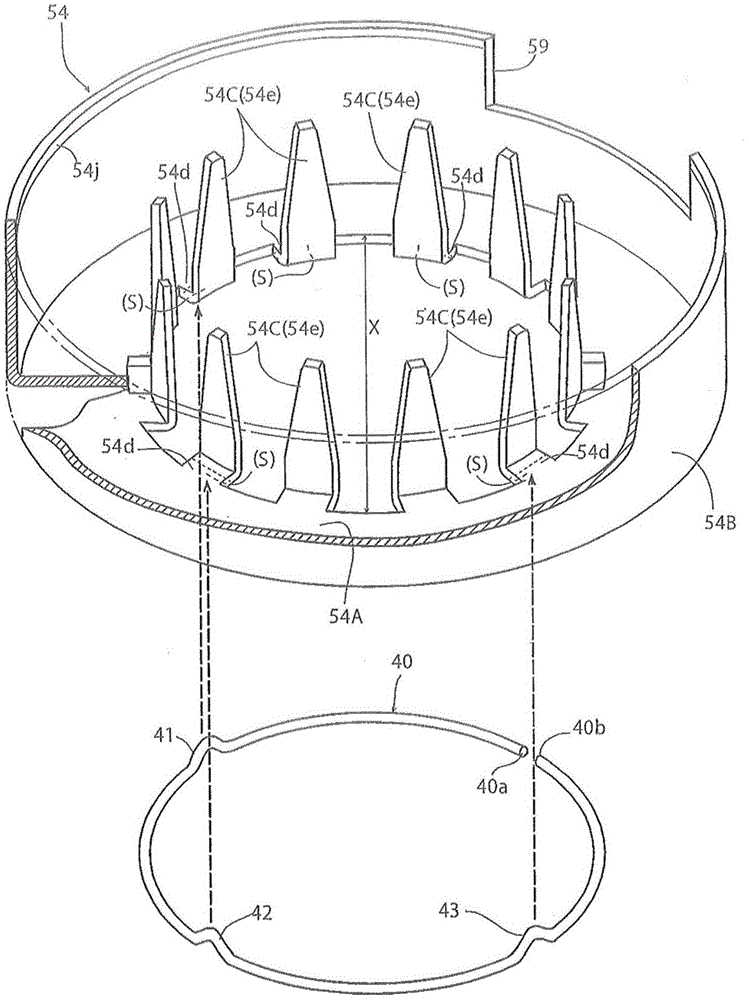
[0059] figure 1 It is a partial cutaway front view showing an embodiment of the electric valve of the present invention, figure 2 is externally embedded in figure 1 A schematic cross-sectional view of the stator part before the housing is shown, image 3 is indicated together with the conduction spring as figure 2 A partial cutaway perspective view of the yoke, one of the structural elements of the stator shown, Figure 4 yes figure 2 Bottom view of the stator (single piece) shown, Figure 5 yes figure 2 Bottom view of the stator in the state shown (state with the anti-rotation member and conduction spring installed).

[0060] The electric valve 1 shown in the figure has the same structure as that described in Patent Document 1, etc., and the lower end portion of a cylindrical housing 20 with a top is hermetically bonded to the valve body 10 by means of...


PUM


Abstract

The present invention provides an electric valve. A stator (50) formed by a die is embedded on housing (20), a rotation stopping part is installed at the lower surface of the stator to prevent the relative rotation of the stator and the valve main body, and the stator has a yoke (54). The yoke has a circle ring panel portion (54A) and the ruled number of unguiform pole teeth (54C) separated in a ruled angle at the inner peripheral side of the circle ring panel portion for punching and folding. A communication spring (40) capable of elastic deformation up and down is installed between the exposure part (S) of the lower surface which is not coated by molding resin of each pole tooth and the rotation stopping part (30). The communication spring takes elastic linear materials with conductivity as raw materials and is bent to be a ring with a gap. Through adoption of the invention, the existing die of an stator or molding formation is not needed to be reformed and is able to restrain the discharge between the unexpected yoke and the housing, so that the bad influence on peripheral loops may be reduced even if the noise of high voltage is applied to a stator coil, and the manufacture cost and the cost of production may be reduced.

Description

technical field [0001] The invention relates to an electric valve, which is suitable for use in heat pump refrigeration and heating systems, etc., and particularly relates to such an electric valve: the casing is sealed and engaged with the valve main body, and the stator is embedded in the casing to match the The inner peripheral rotor is driven to rotate. Background technique [0002] As an electric valve, for example, as can be seen in Patent Document 1, there is known a technology in which a valve chamber, a valve seat (valve port), a valve shaft with a valve core, and an inlet and outlet (catheter joint) are provided. The lower end of a cylindrical housing with a top is sealingly joined to the valve main body, and a rotor is disposed on the inner periphery of the housing with a predetermined gap, and a stator is externally embedded on the housing to The rotor is driven in rotation. [0003] In this kind of electric valve, a screw feed mechanism is provided between the...

Claims


Application Information

Patent Timeline
Patent Type & Authority Applications(China)
IPC IPC(8): F16K31/04F25B41/00F25B41/40
CPCF16K31/041F16K31/046F25B41/00
Inventor 梅泽仁志荒井良太田渊健资
Owner FUJIKOKI MFG CO LTD
Why Eureka
Try Eureka