Size range measuring tool of stepped shaft part and measuring method

A technology of size range and stepped shaft, which is applied in the field of measuring and measuring tools for the size range of stepped shaft parts, can solve the problems such as the inability to measure and reduce the size of the ruler and gauge, and achieve the effect of eliminating hidden quality risks, reducing labor costs and improving work efficiency.

Inactive Publication Date: 2016-02-03
SHENYANG LIMING AERO-ENGINE GROUP CORPORATION
View PDF3 Cites 2 Cited by
  • Summary
  • Abstract
  • Description
  • Claims
  • Application Information

AI Technical Summary

Problems solved by technology

[0002] In the process of engine repair, some parts and components need to be mechanically supplemented due to reasons such as size out-of-tolerance or change of structure. For the step size of some special shapes, machine tools and gauges cannot be measured, which greatly restricts production and processing. For example, due to structural changes, the gear shaft of the original structure needs to be ground. Make it reduce the size in the axial and radial directions, and control it within the qualified size range. The size in the radial direction is guaranteed by the radial feed amount of the grinding machine, but the machine tool cannot guarantee the size in the axial direction, because the gear structure is stepped. , Ordinary measuring tools cannot measure accurately, so there is a great restriction on the machining of gears. It is necessary to design a special fixture and method for measuring the size of the stepped shaft to ensure the dimensional accuracy requirements.

Method used


Image

  • Size range measuring tool of stepped shaft part and measuring method
  • Size range measuring tool of stepped shaft part and measuring method

Examples


Embodiment Construction

[0027] The present invention will be described in further detail below in conjunction with embodiment.

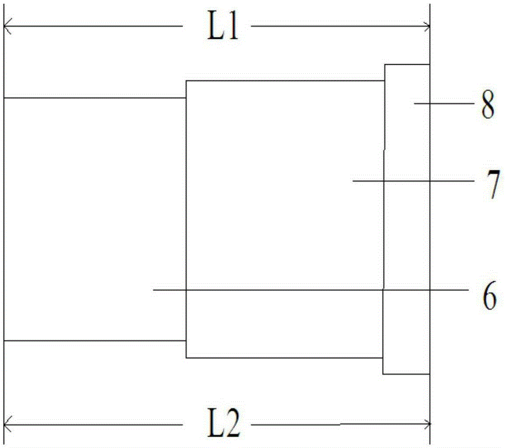
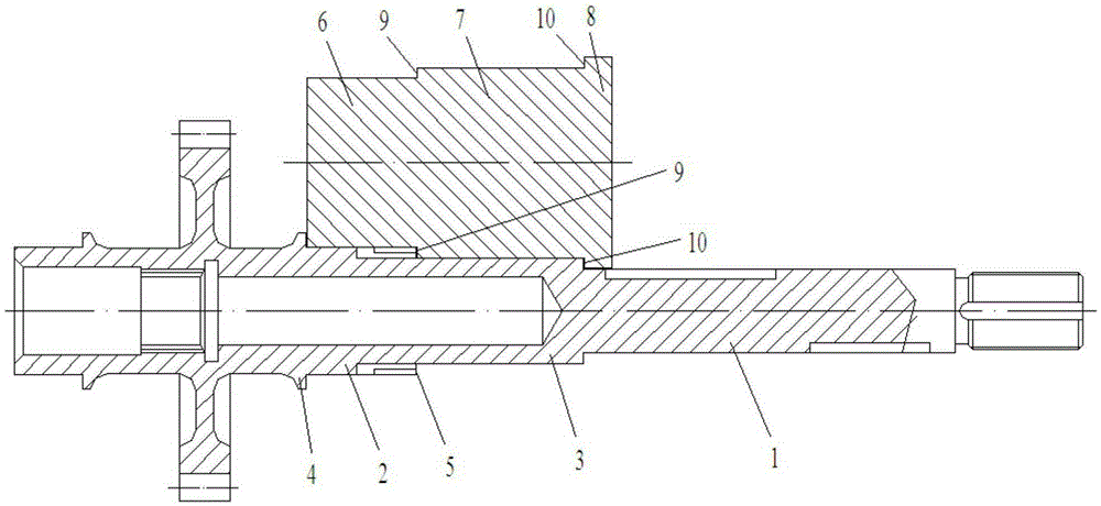
[0028] Such as Figure 1 ~ Figure 2 As shown, a measuring tool for measuring the size range of a stepped shaft part is used to measure the axial dimension of the stepped part of the stepped shaft part. The part 1 at least includes a first section shaft 2 and a second section shaft 3. A shaft shoulder 4 is provided at the end of the shaft 2, a first step 5 is provided between the first section of the shaft 2 and the second section of the shaft 3, and the measuring tool includes a first measuring part 6, a second measuring part 7 and a third measuring part Part 8, the total axial length L of the second measuring part 7 and the first measuring part 6 1 The maximum tolerance value of the length of the step to be measured is reduced by 0.01mm, and the total axial length of the other side is L 2 Then the minimum tolerance value of the length of the step to be measured is increa...


PUM


Abstract

The invention provides a size range measuring tool of a stepped shaft member and a measuring method. The size range measuring tool and the measuring method are used for measuring the axial size of a step part of the stepped shaft member, and the member at least comprises a first segment of shaft and a second segment of shaft. The second segment of shaft is provided with a shaft shoulder, and a first step exists between the first segment of shaft and the second segment of shaft. The measuring tool comprises a first measuring part, a second measuring part and a third measuring part. The axial length of on one side of the second measuring part is the maximum length of the step part to be measured, and the axial length on the side is the minimum length of the step part to be measured. The end surface of the third measuring part is attached to the shaft shoulder on the second segment of shaft. The radial size of the first measuring part is smaller than the radial size of the second measuring part, and the connection part between the first measuring part and the second measuring part forms a second step. The second step is matched with the first step. The radial size of the second measuring part is smaller than the radial size of the third measuring part, and the connection part between the second measuring part and the third measuring part forms a third step. The third step is matched with the end surface of the second segment of shaft.

Description

Technical field: [0001] The invention relates to the technical field of measuring engine parts, in particular to a measuring tool and a measuring method for the size range of stepped shaft parts. Background technique: [0002] In the process of engine repair, some parts and components need to be mechanically supplemented due to reasons such as size out-of-tolerance or change of structure. For the step size of some special shapes, machine tools and gauges cannot be measured, which greatly restricts production and processing. For example, due to structural changes, the gear shaft of the original structure needs to be ground. Make it reduce the size in the axial and radial directions, and control it within the qualified size range. The size in the radial direction is guaranteed by the radial feed of the grinding machine, but the machine tool cannot guarantee the size in the axial direction, because the gear structure is stepped. , Ordinary measuring tools cannot measure accura...

Claims


Application Information

Patent Timeline
Patent Type & Authority Applications(China)
IPC IPC(8): G01B5/00
Inventor 张昱董颖冯硕刘先亮
Owner SHENYANG LIMING AERO-ENGINE GROUP CORPORATION
Why Eureka
Try Eureka