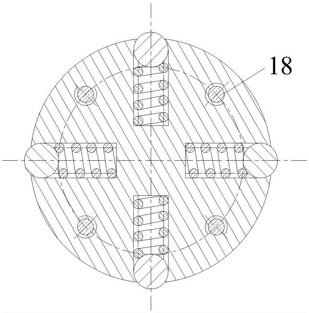
Boring bar special for machining deep hole and inner groove

A groove machining and deep hole technology, applied in boring bars and other directions, can solve the problems of not being suitable for machining deep hole multi-layer annular inner grooves, unable to ensure the axial dimensional accuracy of annular grooves, and not suitable for deep hole machining with small diameters. Achieve the effect of increasing stiffness, reducing deformation, and improving local stiffness

Inactive Publication Date: 2016-06-08
NANJING UNIV OF SCI & TECH
View PDF8 Cites 10 Cited by
  • Summary
  • Abstract
  • Description
  • Claims
  • Application Information

AI Technical Summary

Problems solved by technology

However, the pressure knife spring is easy to be blocked by chips, which makes it impossible to retract the knife, and the reliability is poor. In addition, if you want to process multi-layer annular grooves, you must adjust the axial position of the bushing. The operation is cumbersome, and the gap between the annular grooves cannot be guaranteed Axial dimensional accuracy; and the corresponding guide and support mechanism is not added to the tool bar, so it is not suitable for machining deep-hole multi-layer annular inner grooves
[0008] It can be seen from the above that the existing deep hole inner groove processing technology has poor rigidity of the tool bar, poor flexibility in axial position control, and it is difficult to process multi-layer annular inner grooves, and the radial dimension of the tool bar is large, which is not suitable for small hole diameters. deep hole processing

Method used


Image

  • Boring bar special for machining deep hole and inner groove
  • Boring bar special for machining deep hole and inner groove
  • Boring bar special for machining deep hole and inner groove

Examples


Embodiment

[0038] figure 1 It is a schematic diagram of the overall structure of the special boring bar for segmented deep hole inner groove processing with guide support of the present invention. It is mainly suitable for boring inner grooves of deep and long holes with small diameters, and can also be used for boring inner walls of deep holes. The length to diameter ratio of the boring bar is 18:1, and the diameter of the main body of the tool bar is 20mm. The special boring bar is composed of a guide support part, a cutter head part, a tool feed and retract mechanism, a tool bar part and a hydraulic drive part. The guide support part can provide support for the special boring bar and improve the local rigidity of the cutter head. The tool holder part is made of high elastic modulus material, which can further improve the overall rigidity of the cutter holder.

[0039] The assembly process of the special boring bar of the present invention is as follows: firstly, after connecting the...


PUM

PropertyMeasurementUnit
lengthaaaaaaaaaa
diameteraaaaaaaaaa
lengthaaaaaaaaaa

Abstract

The invention discloses a segmented type boring bar with a guide support part and special for machining a deep and long hole and an inner groove. The boring bar comprises the guide support part, a tool bit part, a feeding and retracting mechanism, a rod body part and a hydraulic drive part. The guide support part comprises a guide head and an auxiliary support part. The guide head is divided into a front guide head body and a rear guide head body which are connected through a screw. The rear guide head body is connected with the front end of a sleeve through a pin, a hydraulic cylinder is connected with the rear end of the sleeve through a pin, and a cutter bar is connected with the bottom of the hydraulic cylinder through a pin. When the inner groove is bored, the guide support part has a supporting effect, and the local static rigidity of the tool bit part can be improved. By means of the feeding and retracting mechanism, the axial positioning and the feeding and retracting movement of the tool can be achieved. The segmented type special tool with the guide support part is suitable for machining the multi-layer inner groove and can also be used for boring the inner wall of the deep and long hole; a blade is symmetrically arranged, so radial force and tangential force counteract, the rigidity of the cutter bar is greatly improved, and machining conditions are remarkably improved.

Description

technical field [0001] The invention belongs to the field of deep hole inner groove processing, in particular to a special boring bar for deep hole inner groove processing. Background technique [0002] In mechanical processing technology, deep hole internal groove boring is always a technical difficulty, because in the process of boring deep hole (length-to-diameter ratio greater than 15) internal groove, the boring tool is in a semi-closed state, and the structural size of the tool bar Restricted by the deep hole, it is generally a slender structure, and the rigidity of the boring bar is weak. Moreover, during the boring process, the tool bar is in an overhanging state. Without guide support, the deformation of the tool head is relatively large, which easily leads to the phenomenon of tool slipping, which seriously affects the machining accuracy of the deep hole inner groove. [0003] In order to solve the problem of stress deformation of boring bars with large length-to-...

Claims


Application Information

Patent Timeline
Patent Type & Authority Applications(China)
IPC IPC(8): B23B29/02
CPCB23B29/02B23B2220/126
Inventor 程寓付乾辰
Owner NANJING UNIV OF SCI & TECH
Why Eureka
Try Eureka